
Automatic hand-eye calibration method and device for optimal calibration point selection and error automatic measurement

A hand-eye calibration and calibration point technology, which is applied in the direction of manipulators, program-controlled manipulators, manufacturing tools, etc., can solve the problems of decreased accuracy, the inability to guarantee the solution of the collected points, and the inconvenience of calibration boards or cameras.

Active Publication Date: 2019-09-17
SPEEDBOT ROBOTICS CO LTD
View PDF8 Cites 27 Cited by
  • Summary
  • Abstract
  • Description
  • Claims
  • Application Information

AI Technical Summary

Problems solved by technology

[0003] Defects and reasons: The hand-eye calibration scheme of walking the teaching point has great defects in installation and use: In terms of installation: there is a large space limitation for fixing, and the fixed installation of the calibration board or camera also brings difficulties to the entire calibration process. Inconvenience
If the rotation pose of the manipulator is not rich enough, the accuracy of the final calibration result will decrease or even be wrong
In extreme cases, if the rotation axis of each rotation of the robotic arm is parallel, it may even cause the calibration equation to be unsolvable
The traditional way is to let the robotic arm walk according to the preset points, but this does not guarantee that the points obtained for each sampling are necessary
[0012] To sum up, the problems existing in the existing technology are: the traditional calibration method cannot realize the automatic positioning of the mechanical arm during the calibration process, the installation and operation process of the camera or the calibration board is complicated; the error measurement method is complicated and there are large errors, and the applicability Not high; in addition, the method of preset fixed positions cannot guarantee that the collected points can meet the needs of solving the calibration equation, and the accuracy and efficiency of solving the equation cannot be guaranteed
[0023] The traditional calibration method requires a human to direct the robotic arm to perform a series of sampling actions under the camera, but it is not only cumbersome to operate the robotic arm for calibration every time, but also the accuracy cannot be guaranteed
The existing automatic calibration method also uses manual teaching. After testing a series of points that the robot can reach, these points are stored for a series of calibration processes. There is no universality. The present invention proposes a The calibration method that can automatically find the best sampling point and judge the sampling results, and according to the motion characteristics of the industrial robot itself, design the sampling point design that the industrial robot is easy to reach, from the point design of the calibration process at the beginning, the data Acquisition and error analysis processes do not require external personnel to design, and truly realize the intelligent realization of the entire calibration process

Method used


Image

  • Automatic hand-eye calibration method and device for optimal calibration point selection and error automatic measurement
  • Automatic hand-eye calibration method and device for optimal calibration point selection and error automatic measurement
  • Automatic hand-eye calibration method and device for optimal calibration point selection and error automatic measurement

Examples


Embodiment

[0291] (1) Eye-in-hand one-click calibration test on the sawyer robot:

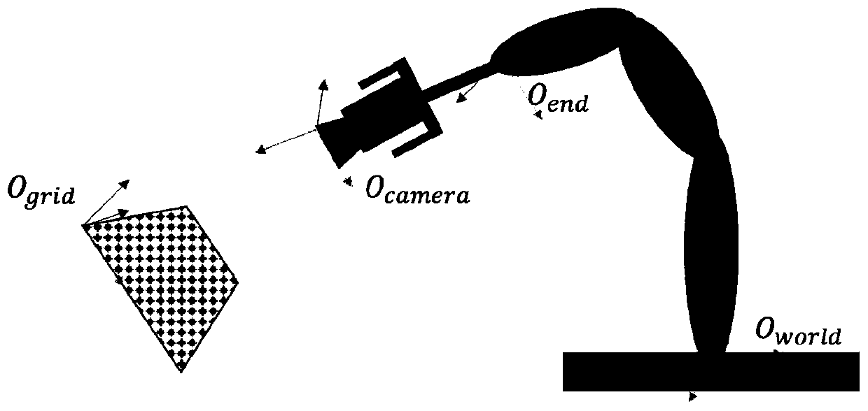
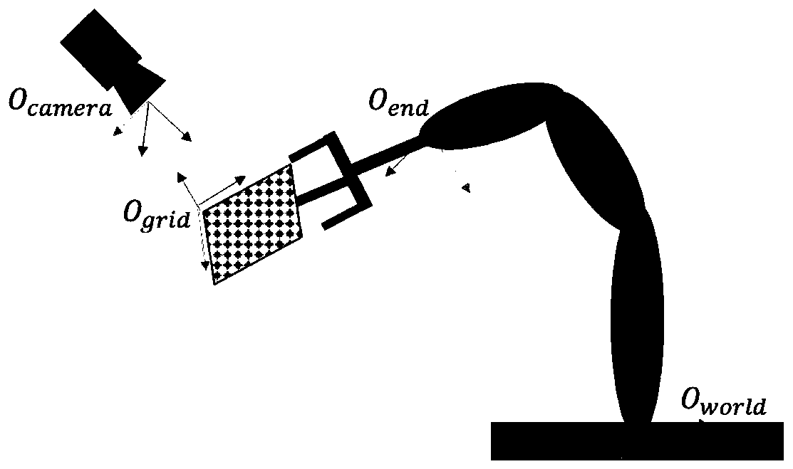
[0292] a) The robot holds the camera and moves around itself to detect whether there is a calibration plate around (such as Figure 11 shown).

[0293] b) The camera detects the existence of the calibration plate, and the robot holds the camera and moves in different directions to estimate the orientation of the calibration plate in the robot coordinate system (such as Figure 12 shown).

[0294] c) The robot estimates the position of the calibration plate, and at this time the end of the mechanical arm has moved directly above the calibration plate (such as Figure 13 shown).

[0295] d) The robot takes the estimated position of the calibration plate as the center, rotates and samples the calibration plate, and records the position of the end of the mechanical arm in the camera coordinate system (such as Figure 14 shown).

[0296] e) Solving the calibration equation, the data collected during the c...


PUM


Abstract

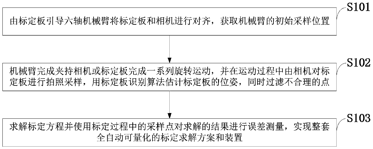
The invention belongs to the technical field of relative position calibration between a camera and a robot, and discloses an automatic hand-eye calibration method and device for optimal calibration point selection and error automatic measurement. The method comprises the following steps that a calibration plate guiding six-axis mechanical arm is used for aligning a calibration plate with the camera, and an initial sampling position of the mechanical arm is obtained; the mechanical arm clamps the camera or the calibration plate to complete a series of rotary movements, photographing and sampling are carried out on the calibration plate by the camera in the movement process, a calibration plate recognition algorithm is used for estimating the pose of the calibration plate, and meanwhile, unreasonable points are filtered out; and a calibration equation is solved, error measurement is conducted on a solution result by using sampled points in the calibration process so as to realize a fully-automatic quantifiable calibration solution scheme and device. According to the method, an obtained calibration error can be quantified in various dimensions such as rotation and translation, the whole calibration process can be guaranteed to be automatic, accurate and efficient, and the problems of eye in hand calibration and eye to hand calibration in practical application are solved.

Description

technical field [0001] The invention belongs to the technical field of relative position calibration between a camera and a robot, and in particular relates to an automatic hand-eye calibration method and device for optimal calibration point selection and error self-measurement. Background technique [0002] Existing technology: At present, the hand-eye calibration system with automatic guidance, automatic positioning of sampling points and error measurement is still vacant in the technical field of calibration. The traditional automatic calibration method is to fix the calibration board or the camera at a certain position, and use the manual teaching method to let the robot arm go through the fixed moving point process (such as walking in a square or circle) that has been tested in advance to control the movement of the robot arm and let the camera Sampling the calibration board, that is, when the system is installed, where the robotic arm should go to sample is fixed and d...

Claims


Application Information

Patent Timeline
Patent Type & Authority Applications(China)
IPC IPC(8): B25J9/16
CPCB25J9/1692
Inventor 黄金赵航陈飞
Owner SPEEDBOT ROBOTICS CO LTD
Learn More