Decorative lamp with optical structure

An optical structure and lamp technology, applied in the field of lighting, can solve the problems of high cost and difficult to realize frame, and achieve the effect of low cost, simple structure and good display effect.

Inactive Publication Date: 2019-09-17
JIANGSU IRON ANCHOR GLASS LTD BY SHARE LTD
View PDF6 Cites 0 Cited by
  • Summary
  • Abstract
  • Description
  • Claims
  • Application Information

AI Technical Summary

Problems solved by technology

Therefore, it can be concluded that it is difficult to achieve a design with a frame of less than 8mm in this way, unless the size of the LED light bar spacing is reduced and realized in a costly manner

Method used


Image

  • Decorative lamp with optical structure
  • Decorative lamp with optical structure
  • Decorative lamp with optical structure

Examples


Embodiment 1

[0039] as the picture shows:

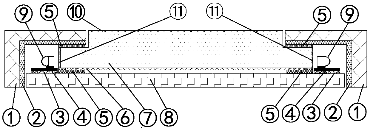
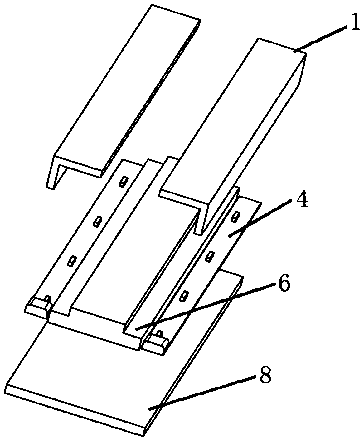
[0040] Such as Figure 1 to Figure 4 As shown, a decorative lamp with an optical structure includes a stack structure, and the stack structure includes a lamp frame 1, a reflective medium 2, a thermally conductive fixing glue 3, a three-color full-color LED strip 4, a structural fixing glue 5, and an optical network point 6 , light guide glass 7, lamp bottom shell 8, LED light emitting surface 9, light guide glass light emitting surface 10, light guide glass light entering surface 11, the lamp frame 1 is made of plastic or metal, and is used to cover the LED light strip body Structure and cover the bright and dark spot area of ​​the LED, so that the light effect defects of the bright and dark spot of the LED are covered in the frame of the lamp, and the area cannot be seen by the naked eye;

[0041] The reflective medium 2 is a layer of reflective film formed on the inner surface of the light-shielding bracket through processes such as polishing...

Embodiment 2

[0064] Such as Figure 1 to Figure 4 As shown, this embodiment will explain its principle in detail. At present, lamps with ultra-narrow bezel or no bezel are popular. From the above analysis, it is known that it is necessary to reduce the spacing of LED light bars, which will inevitably lead to an increase in cost.

[0065] This application provides a light mixing lamp with a secondary optical structure. On the basis of the original primary optical mixing light lamp, while keeping the distance between the LED light bars unchanged, the LED light bars use LED chips as side-emission methods. If the chip is forward incident, it will not improve the light mixing distance. It can only reduce the thickness of the lamp and increase the frame width of the lamp. By adjusting the incident direction of the LED chip, that is, the way of reverse incident, it can be obvious Reduce the light mixing distance W1 of bright and dark spots, so as to reduce the width of the lamp frame and achieve ...

Embodiment approach

[0088] As the best functional implementation of this device invention: the control system of the decorative lighting circuit is powered on to turn on the three-color full-color LED strip light, and the light emitted by the LED light-emitting surface shoots towards the reflective medium, and the light is reflected back through the reflective medium. Mix light in the light mixing area covered by the lamp frame to obtain uniform mixed light, and the uniformly mixed light reflects light through the optical dots under the light guide glass to the light exit surface of the light guide glass, forming a colorful atmospheric optical scene effect in the air.


PUM


Abstract

The invention discloses a decorative lamp with an optical structure. The decorative lamp is characterized by comprising a stack structure. The stack structure comprises a lamp frame, a reflection medium, a heat conduction fixing glue, a three-primary-color full-color LED lamp strip, a structure fixing glue, optical lattice points, light guide glass, a lamp bottom shell, an LED light-emitting face, a light guide glass light-emitting face and a light guide glass light-incident face. The lamp frame is made of plastic or metal materials and is used for shielding the LED lamp strip body structure and the LED light and dark spot area. Therefore, the LED light and dark spot light effect defect is shielded in the lamp frame, and the area which cannot be seen by naked eyes is shielded.

Description

technical field [0001] The invention relates to the lighting field, in particular to a decorative lamp with an optical structure. Background technique [0002] At present, decorative lamps are generally used to attract people's attention, such as traffic lights, decorative lights on the exterior walls of buildings, and decorative lights on billboards. At present, the decorative lamps on the market are mainly based on LED light sources. Since the light emitted by a single-point LED light source is linear and has a certain spatial angle, the light incident from multiple single-point LED light sources in a row into the space medium will be near the light source. Form a mixed light area with uneven light and dark. If the light and dark mixed light area is not treated with optical structure, the uneven light and dark light will directly enter the eyes of people, and people will see the phenomenon of uneven light and dark spots. Bad experience effect of visual vertigo. [0003] ...

Claims


Application Information

Patent Timeline
IPC IPC(8): F21S8/00F21V1/00F21V7/28F21V8/00F21Y115/10
CPCF21S8/00F21V1/00F21V2200/00F21Y2115/10F21V7/28
Inventor 吴贲华
Owner JIANGSU IRON ANCHOR GLASS LTD BY SHARE LTD
Why Eureka
Try Eureka