
A wall positioning device for a prefabricated building

A positioning device and construction technology, applied in the direction of using optical devices, measuring devices, instruments, etc., can solve the problems of complicated operation process, low installation efficiency, hard to see, etc., to improve accuracy, facilitate disassembly and assembly, and ensure accuracy Effect

Inactive Publication Date: 2020-06-12
青岛滨海建设集团有限公司
View PDF19 Cites 0 Cited by
  • Summary
  • Abstract
  • Description
  • Claims
  • Application Information

AI Technical Summary

Problems solved by technology

[0002] In the process of home decoration, to install equipment on the wall, you need to use an electric drill to drill holes on the wall, and you need to determine the reference position of the hole before drilling. The traditional method is to use a ruler to measure, and determine the size of the hole through the horizontal and vertical dimensions. The position of the hole, whether the ruler is in the horizontal or vertical position during the measurement process, requires manual visual observation, and there is a large error. Even if a level ruler is used, manual observation is still required, and the slight inclination is difficult to see, and it is determined After the position needs to be marked on the wall, so that the ruler can be removed for the punching process later
The whole operation process is complicated and slow, and the installation efficiency is low

Method used


Image

  • A wall positioning device for a prefabricated building
  • A wall positioning device for a prefabricated building
  • A wall positioning device for a prefabricated building

Examples


Embodiment Construction

[0020] Combine below Figure 1-Figure 5 The present invention is described in detail, and for convenience of description, the orientations mentioned below are now stipulated as follows: figure 1 The up, down, left, right, front and back directions of the projection relationship itself are the same.

[0021] The present invention relates to a wall positioning device for prefabricated buildings, which is mainly used in the process of installing things on the wall. The present invention will be further described below in conjunction with the accompanying drawings of the present invention:

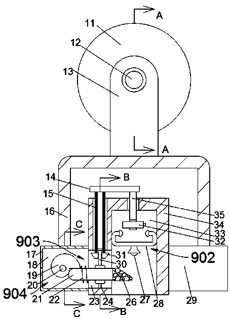
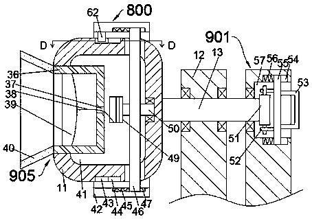
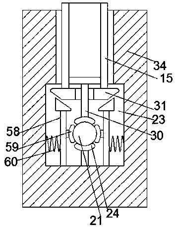
[0022] A wall positioning device for a prefabricated building according to the present invention includes an air extraction box 11, the front end surface of the air extraction box 11 is fixed with a fixed shaft 13, and the array on the fixed shaft 13 has rotatable Two swing arms 12, the swing arm 12 on the front side is provided with a connecting groove 57 opening forward, and a locking devic...


PUM


Abstract

The invention discloses a fabricated wall positioning device for buildings. The fabricated wall positioning device comprises a suction box, wherein a fixed shaft is fixedly arranged on the end surface of the front side of the suction box; two rotating swing arms are arrayed on the fixed shaft; an engagement groove with a forward opening is formed in the swing arm at the front side; and a lock device is arranged in the engagement groove. According to the fabricated wall positioning device, the thickness, of interfering with direct light, of a cover is adjusted through a curvature wheel by using the principle that the irradiation distance of the light can be limited by the cover, and the position of an end point of the light is adjusted in a readable manner, so that the machining accuracy is ensured; by adopting a suction pump-type piston structure, equipment is absorbed to a wall space by using atmospheric pressure, so that disassembly and assembly are facilitated; the principle that the center of gravity is vertically downward is utilized as a criterion of judging the vertical direction and judgment through manual visual observation is not needed, so that an artificial subjective judgment error is avoided; and the horizontal direction is determined perpendicular to a vertical line by adopting a lockable swing arm structure, so that the accuracy is improved.

Description

technical field [0001] The invention relates to the technical field of wall surface processing and positioning, in particular to a wall body positioning device for an assembled building. Background technique [0002] In the process of home decoration, to install equipment on the wall, you need to use an electric drill to drill holes on the wall, and you need to determine the reference position of the hole before drilling. The traditional method is to use a ruler to measure, and determine the size of the hole through the horizontal and vertical dimensions. The position of the hole, whether the ruler is in the horizontal or vertical position during the measurement process, requires manual visual observation, and there is a large error. Even if a level ruler is used, manual observation is still required, and the slight inclination is difficult to see, and it is determined After the position needs to be marked on the wall, so that the ruler can be removed for the punching proces...

Claims


Application Information

Patent Timeline
Patent Type & Authority Patents(China)
IPC IPC(8): G01B11/00
CPCG01B11/00
Inventor 张国强
Owner 青岛滨海建设集团有限公司
Learn More