Correction Method of Ultrasonic Flowmeter with Frequency Drift Correction Function

A frequency drift, ultrasonic technology, used in the measurement of flow/mass flow, liquid/fluid solid measurement, measurement devices, etc., can solve the problem of different degrees of resonance drift, affecting the measurement accuracy and stability of ultrasonic flowmeters, and the frequency of the driving signal. Unable to maintain consistency and other problems, to achieve the effect of ensuring echo quality, realizing automatic gain control, and improving accuracy and quality

Active Publication Date: 2020-05-19
智驰华芯(无锡)传感科技有限公司
View PDF8 Cites 1 Cited by
  • Summary
  • Abstract
  • Description
  • Claims
  • Application Information

AI Technical Summary

Problems solved by technology

[0004] However, the resonant frequency of the ultrasonic transducer will be affected by the ambient temperature, and will also drift with the aging of the transducer, so that the resonant frequency of the transducer deviates from the frequency of the driving signal, while the upstream and downstream transducers in the ultrasonic flowmeter The degree of resonance drift may be different. The drift of the resonance frequency makes the resonance frequency of the upper and lower transducers inconsistent with the frequency of the driving signal, thus affecting the measurement accuracy and stability of the ultrasonic flowmeter.

Method used


Image

  • Correction Method of Ultrasonic Flowmeter with Frequency Drift Correction Function
  • Correction Method of Ultrasonic Flowmeter with Frequency Drift Correction Function
  • Correction Method of Ultrasonic Flowmeter with Frequency Drift Correction Function

Examples


Embodiment Construction

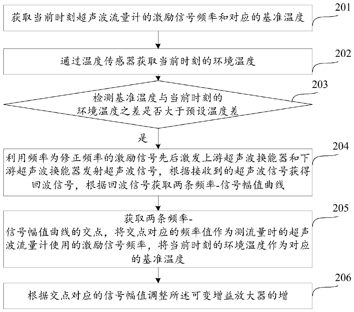
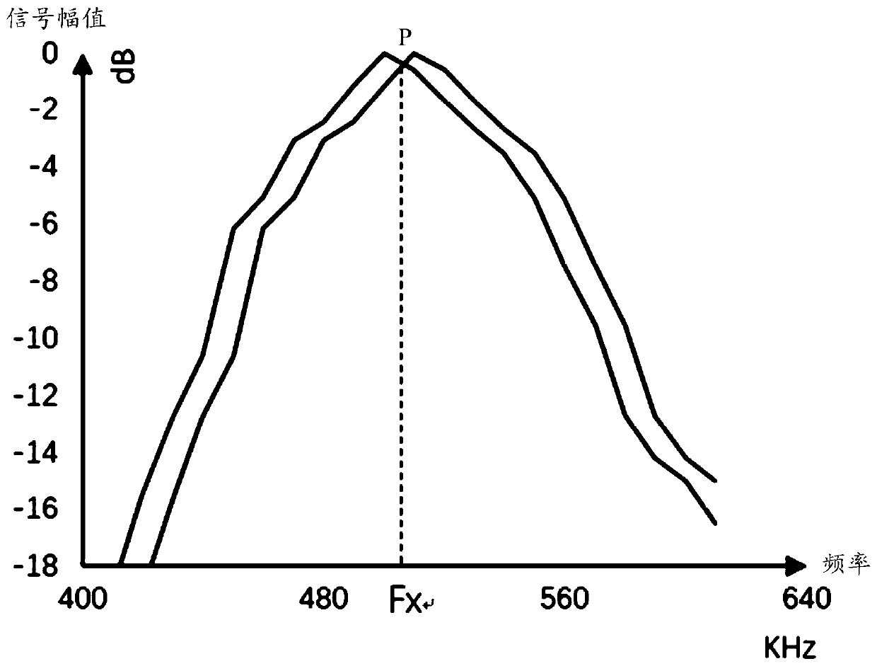
[0032] In order to make the object, technical solution and advantages of the present invention clearer, the implementation manner of the present invention will be further described in detail below in conjunction with the accompanying drawings.

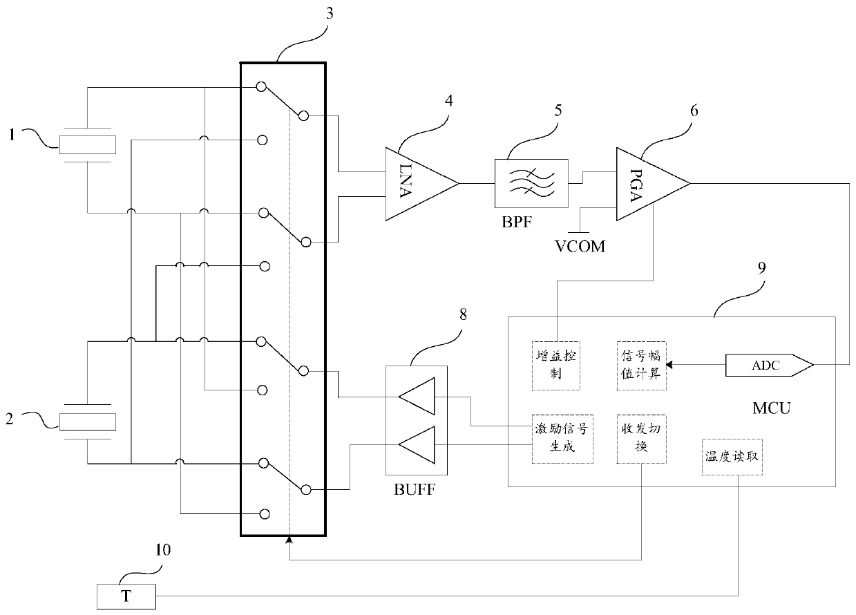
[0033] Such as figure 1 As shown, the embodiment of the present application provides a structural block diagram of an ultrasonic flowmeter with a frequency drift correction function, including an upstream transducer 1, a downstream transducer 2, a signal switching switch 3, a low noise amplifier 4, and a bandpass filter Device 5, variable gain amplifier 6, microcontroller 9, temperature sensor 10, excitation signal buffer 8, analog-to-digital converter ADC.

[0034] The upstream transducer 1 and the downstream transducer 2 are respectively connected to the signal switching switch 3; through the signal switching switch, the upstream transducer 1 and the downstream transducer 2 are alternately used as the transmitting transducer and the ...


PUM


Abstract

The invention discloses an ultrasonic flowmeter with a frequency drift correction function and a correction method thereof, and belongs to the field of ultrasonic flowmeters. The ultrasonic flowmeter comprises an upstream transducer, a downstream transducer, a signal change-over switch, a low noise amplifier, a bandpass filter, a variable gain amplifier, a microcontroller, a temperature sensor and an excitation signal buffer; the upstream transducer and the downstream transducer are separately connected with the signal change-over switch, and the signal change-over switch is separately connected with the low noise controller and the excitation signal buffer; the low noise amplifier is connected with the bandpass filter, the bandpass filter is connected with the variable gain amplifier, and the variable gain controller is connected with the microcontroller; the microcontroller is connected with the excitation signal buffer and the temperature sensor. The problem that the existing ultrasonic flowmeter is inaccurate in measurement result due to the resonant frequency drift of the transducers is solved; and the effects of improving the measurement accuracy of the time difference of the ultrasonic flowmeter and improving the measurement accuracy of the ultrasonic flowmeter are achieved.

Description

technical field [0001] Embodiments of the present invention relate to the field of ultrasonic flowmeters, in particular to an ultrasonic flowmeter with a frequency drift correction function and a correction method thereof. Background technique [0002] The working principle of the ultrasonic flowmeter that uses the time difference method to measure the flow of the medium is: calculate the flow velocity of the medium according to the difference between the propagation time of the ultrasonic signal downstream and the upstream propagation time, and then determine the volume flow of the medium according to the physical parameters of the pipeline. [0003] In the existing ultrasonic flowmeter, a square wave signal with the same frequency as the resonance frequency of the ultrasonic transducer is generally generated, and the square wave signal is used to drive the upstream and downstream ultrasonic transducers respectively, so that the ultrasonic transducer works in series resonanc...

Claims


Application Information

Patent Timeline
Patent Type & Authority Patents(China)
IPC IPC(8): G01F1/66
CPCG01F1/668
Inventor 夏登明胡国俊
Owner 智驰华芯(无锡)传感科技有限公司
Why Eureka
Try Eureka