
High-precision wide-range gas flow measuring device

A technology of gas flow and measuring devices, which is applied in the direction of volume flow measuring devices, measuring devices, liquid/fluid solid measurement, etc., can solve problems such as inaccurate measurement results, achieve inaccurate measurement results, improve accuracy, and avoid disassembly The effect of the operation

Inactive Publication Date: 2018-11-02
ZHENGZHOU YUTONG BUS CO LTD
View PDF2 Cites 0 Cited by
  • Summary
  • Abstract
  • Description
  • Claims
  • Application Information

AI Technical Summary

Problems solved by technology

[0004] The invention provides a high-precision wide-range gas flow measurement device, which is used to solve the technical problem of inaccurate measurement results caused by disassembling the flowmeter in the prior art

Method used


Image

  • High-precision wide-range gas flow measuring device
  • High-precision wide-range gas flow measuring device
  • High-precision wide-range gas flow measuring device

Examples


Embodiment 1

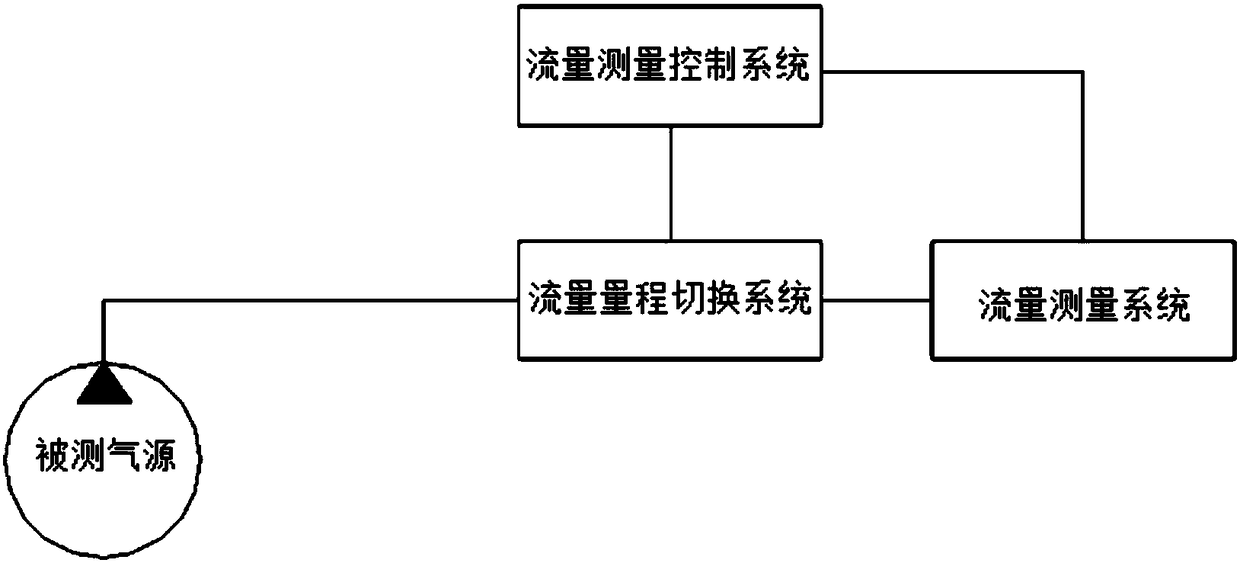
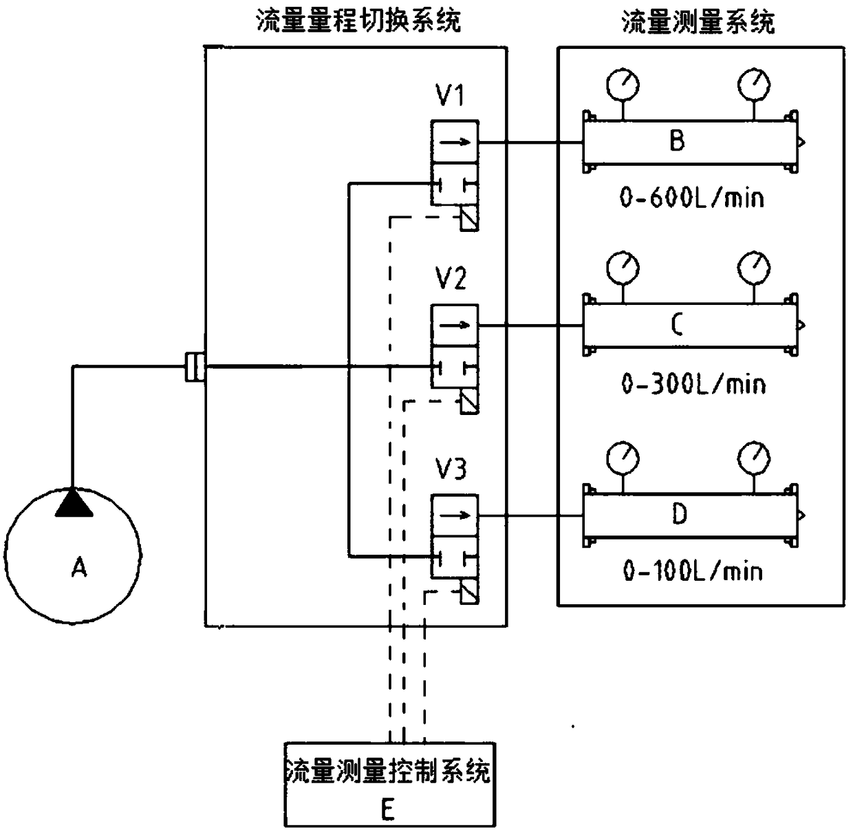
[0021] Such as figure 2 As shown, the gas measured by the high-precision wide-range gas flow measurement device of this embodiment comes from the air compressor A of the measured gas source, the flow measurement control system E is a controller with computing power, and the measurement range switching system includes V1, V2, V3 has three solenoid valves, and the flow measurement system is composed of three flowmeters B, C, and D. The solenoid valves V1, V2, and V3 correspond to the three flowmeters B, C, and D respectively to form a measurement branch. The above solenoid valve controls the conduction and disconnection of the measurement branch.

[0022] The flowmeters are arranged continuously according to the high-precision interval gradient. For example, the flowmeter B in this embodiment has a range of 0-600L / min, and a high-precision measurement interval of 200L / min-300L / min; the flowmeter C has a range of 0-300L / min, the high-precision measurement range is 100L / min-200L...

Embodiment 2

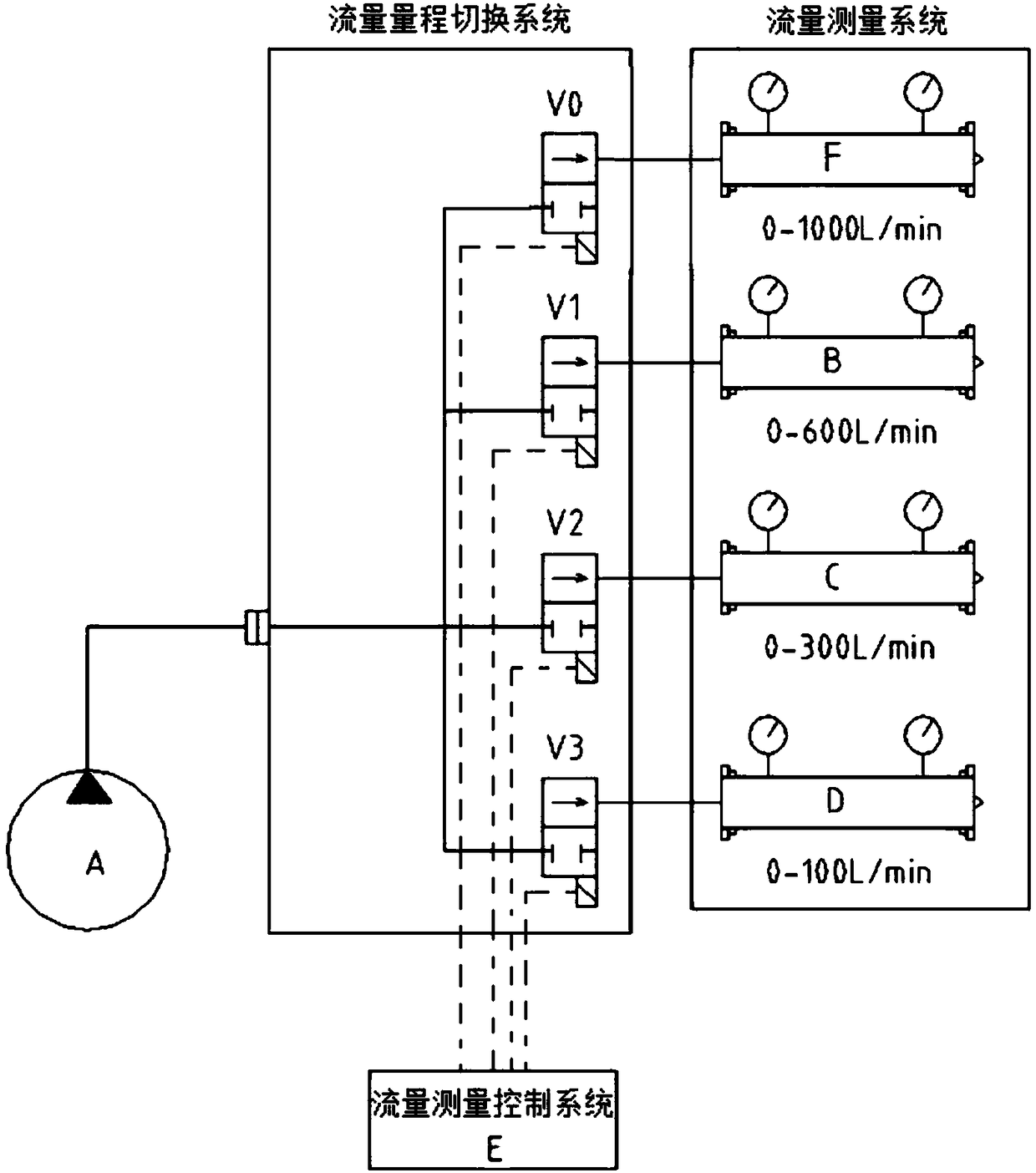
[0027] Such as image 3 As shown, the only difference from Embodiment 1 is that the system also includes a rough flow measurement branch, one end of the flow rough measurement branch is connected to the short-connected ends of the measurement branches, and the flow rough measurement branch is provided by From upstream to downstream, there are coarse measuring solenoid valve V0 and a rough measuring flowmeter F with a large range. Before the measurement, open the rough measurement solenoid valve and close the rest of the solenoid valves. The high-precision wide-range gas flow measurement device collects the gas generated by the gas source, first transmits it to the rough measurement branch, and performs preliminary measurement by the rough measurement flowmeter F. The measured value is transmitted to the flow measurement control system through the sampling line. The flow measurement control system compares the measured value with the high-precision intervals of all measuring br...


PUM


Abstract

The invention discloses a high-precision wide-range gas flow measuring device. The high-precision wide-range gas flow measuring device comprises at least two measuring branches, and one end of each measuring branch is short-circuited to be connected with an interface used for being connected with a to-be-measured gas source; a corresponding switch valve and a flow meter are sequentially arranged on each measuring branch from upstream to downstream. The device further comprises a measurement control system, wherein the measurement control system is in control connection with the switch valves through control lines and in sampling connection with the flow meters through sampling lines. The measuring branches are used, the number of the measuring branches can be increased according to needs,the measuring branches can be automatically selected during gas flow measurement through processing of the measurement control system, the automation degree is high, the problem of inaccurate measurement results caused by disassembly and assembly is solved, the flow measuring precision is improved, and the high-precision measuring range of the measuring device is expanded.

Description

technical field [0001] The invention belongs to the field of gas flow measurement, in particular to a high-precision wide-range gas flow measurement device. Background technique [0002] At present, different kinds of gases are used in many fields, and it is particularly important to accurately measure the gas flow during use. For example, the braking system of commercial vehicles mostly uses air brakes, which require on-board air sources to drive compressed air to provide braking force for the brakes. Commercial vehicles have the characteristics of many types of models and large differences in technical parameters between models. Therefore, the exhaust volume of the vehicle-mounted air source system for different types of vehicles is significantly different. For the test device for air source gas production test A wide, high-precision measurement range is required. [0003] The existing measurement method is to use a single flowmeter in the laboratory to detect the exhaus...

Claims


Application Information

Patent Timeline
Patent Type & Authority Applications(China)
IPC IPC(8): G01F7/00
CPCG01F7/00
Inventor 张辉辉
Owner ZHENGZHOU YUTONG BUS CO LTD
Learn More