
High temperature resistant electromagnetic shielding copper wire

An electromagnetic shielding and high temperature resistant technology, applied in the direction of circuits, insulated cables, electrical components, etc., can solve the problem of poor performance of tinned copper wires in high temperature resistance, corrosion resistance, lack of electromagnetic shielding ability, and long service life of tinned copper wires Short and other problems, to increase the anti-seismic performance, ensure the service life, and prevent the effect of moisture and corrosion

Pending Publication Date: 2019-09-17
山东天厚新材料科技有限公司
View PDF7 Cites 2 Cited by
  • Summary
  • Abstract
  • Description
  • Claims
  • Application Information

AI Technical Summary

Problems solved by technology

[0004] However, the existing tinned copper wires have relatively poor performance in high temperature resistance and corrosion resistance, which will cause difficulties and economic losses to enterprises during use.
Moreover, the copper matrix in the existing tinned copper wire will diffuse to the tinned layer, which affects the solderability of the lead wire, and does not have electromagnetic shielding capability. At the same time, the existing tinned copper wire external protection structure is too simple, which makes the copper wire easy to Deformation under pressure, the outer surface is also easy to be damaged by hand friction, the internal structure is exposed, resulting in a short service life of the tinned copper wire

Method used


Image

  • High temperature resistant electromagnetic shielding copper wire
  • High temperature resistant electromagnetic shielding copper wire
  • High temperature resistant electromagnetic shielding copper wire

Examples


Embodiment Construction

[0026] The following will clearly and completely describe the technical solutions in the embodiments of the present invention with reference to the accompanying drawings in the embodiments of the present invention. Obviously, the described embodiments are only some, not all, embodiments of the present invention. Based on the embodiments of the present invention, all other embodiments obtained by persons of ordinary skill in the art without making creative efforts belong to the protection scope of the present invention.

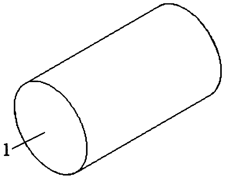
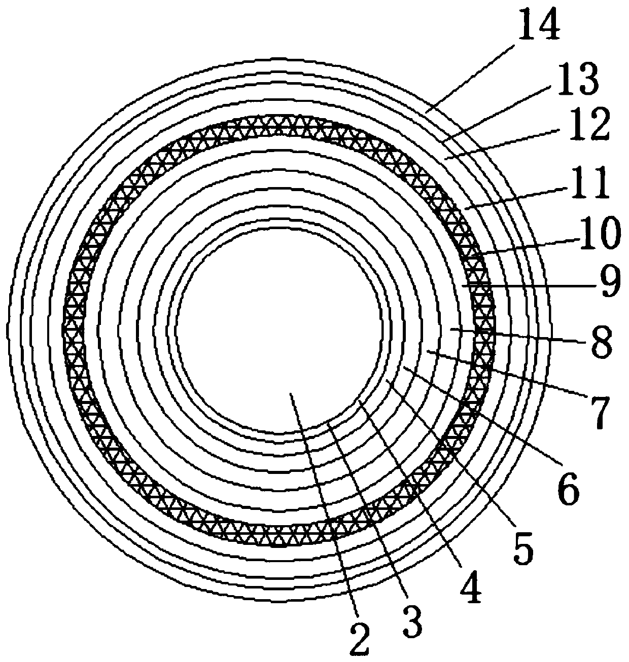
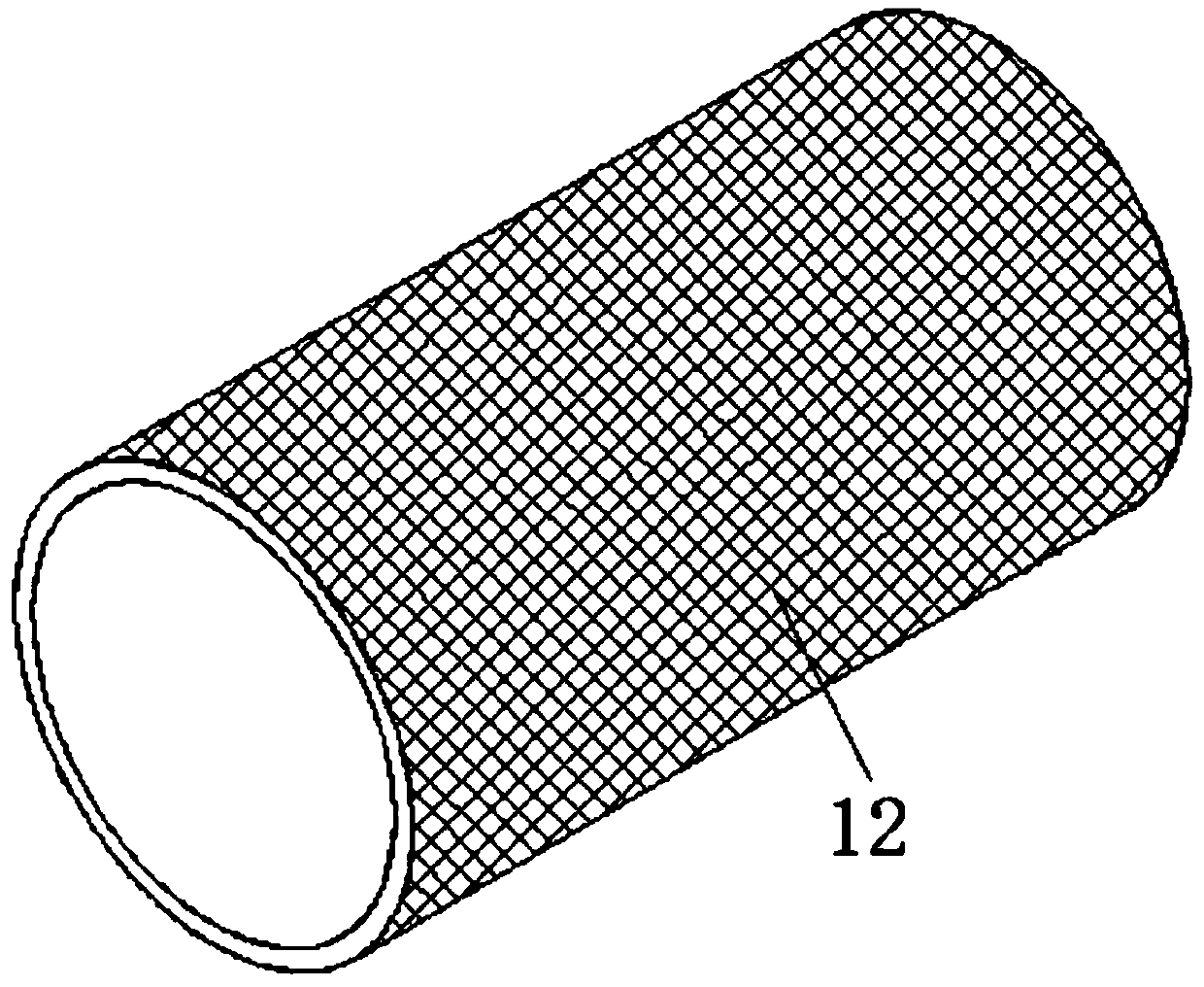
[0027] see Figure 1-3 , the present invention provides a technical solution: a high temperature resistant electromagnetic shielding copper wire, including a copper wire 1;

[0028] Copper wire 1: The copper wire 1 includes an inner copper core 2, and a layer of separation film 3 is provided between the copper core 2 and the tin-plated layer 4. The separation film 3 is a polyethylene film, which is convenient to prevent the copper matrix in the copper core 2 f...


PUM


Abstract

The invention discloses a high temperature resistant electromagnetic shielding copper wire, comprising a copper wire. The copper wire comprises an inner copper core. The outer part of the copper core is sleeved with a tin plating layer. The outer part of the tin plating layer is sleeved with a fixed layer. The outer part of the fixed layer is sleeved with a waterproof layer. The outer part of the waterproof layer is sleeved with a fireproof layer. The outer part of the fireproof layer is sleeved with a flame retardant layer. As for the high temperature resistant electromagnetic shielding copper wire, a separation layer is disposed between the copper core and the tin plating layer so that the copper matrix can be effectively prevented from diffusing into the tin plating layer; the waterproof layer is arranged to effectively prevent the internal structure from being eroded and rusted; at the same time, the fireproof layer and the flame retardant layer are provided, which can effectively protect the internal structure from fire; and an electromagnetic isolation layer is provided, which can effectively prevent external electromagnetic interference when the tinned copper wire is used. The plurality of protective layers are provided so that the internal structure is protected, the service life of the tinned copper wire is prolonged, and the waste of resources is reduced, which can effectively solve the problems in the background art.

Description

technical field [0001] The invention relates to the technical field of copper wires, in particular to a high-temperature resistant electromagnetic shielding copper wire. Background technique [0002] In daily life, copper wires are commonly used as wires, which have good electrical conductivity and are widely used in the manufacture of wires, cables, brushes, etc.; with good thermal conductivity, they are often used to manufacture magnetic instruments and instruments that must prevent magnetic interference, such as compasses and aviation instruments etc.; excellent plasticity, easy to process by hot pressing and cold pressing, and can be made into copper materials such as tubes, rods, wires, strips, strips, plates, foils, etc. [0003] At present, tinned copper wire is mainly used for rubber-insulated mining cables, flexible wires, flexible cables and marine cables as conductive cores, as well as outer shielding braids and brush wires for cables, which can prevent the insula...

Claims


Application Information

Patent Timeline
IPC IPC(8): H01B7/00H01B7/17H01B7/18H01B7/28H01B7/282H01B7/29H01B7/295
CPCH01B7/0009H01B7/17H01B7/1875H01B7/189H01B7/2825H01B7/295H01B7/29H01B7/2806
Inventor 刘冬李曼杨延远孟红军侯红明韩照亮
Owner 山东天厚新材料科技有限公司
Learn More