Glue removing machine clamping spindle

A spindle and glue machine technology, which is applied in the manufacture of electrical components, semiconductor/solid-state devices, circuits, etc., can solve problems such as position deviation and inaccurate positioning, achieve fast clamping or loosening, and realize fine-tuning of clamping force, The effect of preventing damage

Active Publication Date: 2019-09-17
宁波润华全芯微电子设备有限公司
View PDF4 Cites 2 Cited by
  • Summary
  • Abstract
  • Description
  • Claims
  • Application Information

AI Technical Summary

Problems solved by technology

The glue remover is used to remove glue from the wafer. The spindle of the glue remover is a very critical part. The existing spindle of the glue remover is generally inaccurate when positioning the wafer, and it is prone to position deviation.

Method used


Image

  • Glue removing machine clamping spindle
  • Glue removing machine clamping spindle
  • Glue removing machine clamping spindle

Examples


Embodiment Construction

[0021] The specific implementation manners of the present invention will be further described in detail below in conjunction with the accompanying drawings and embodiments. The following examples are used to illustrate the present invention, but are not intended to limit the scope of the present invention.

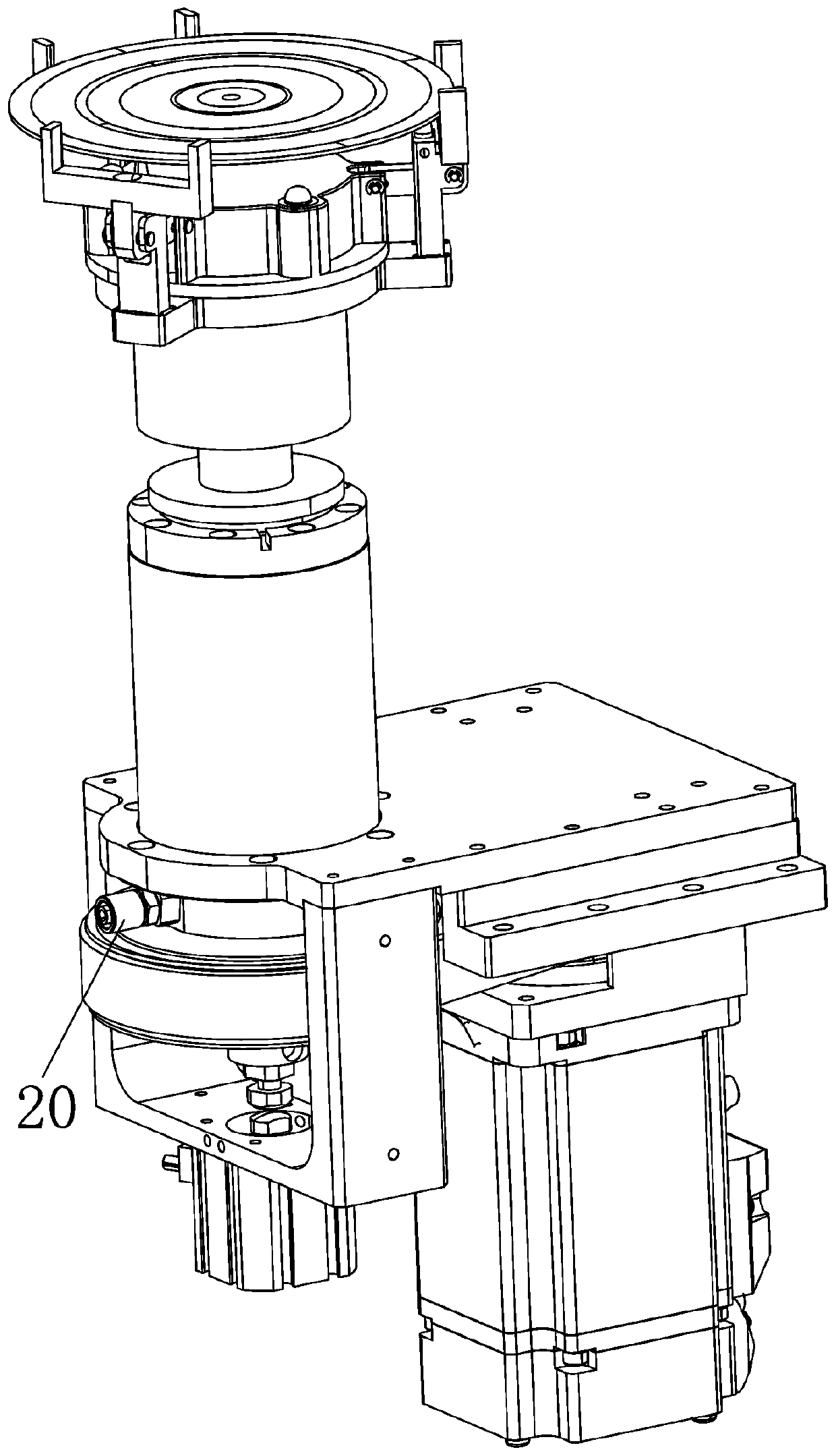
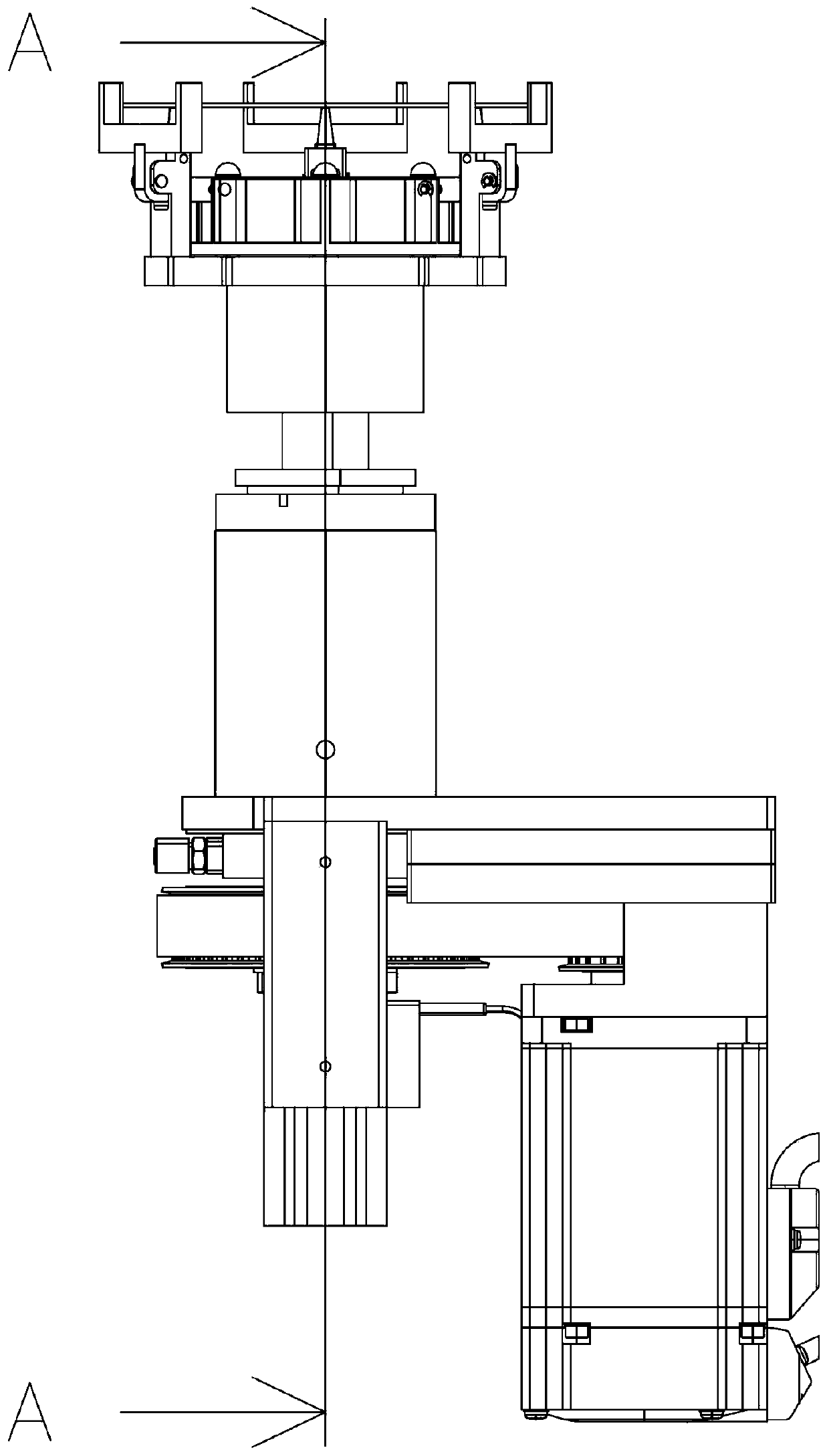
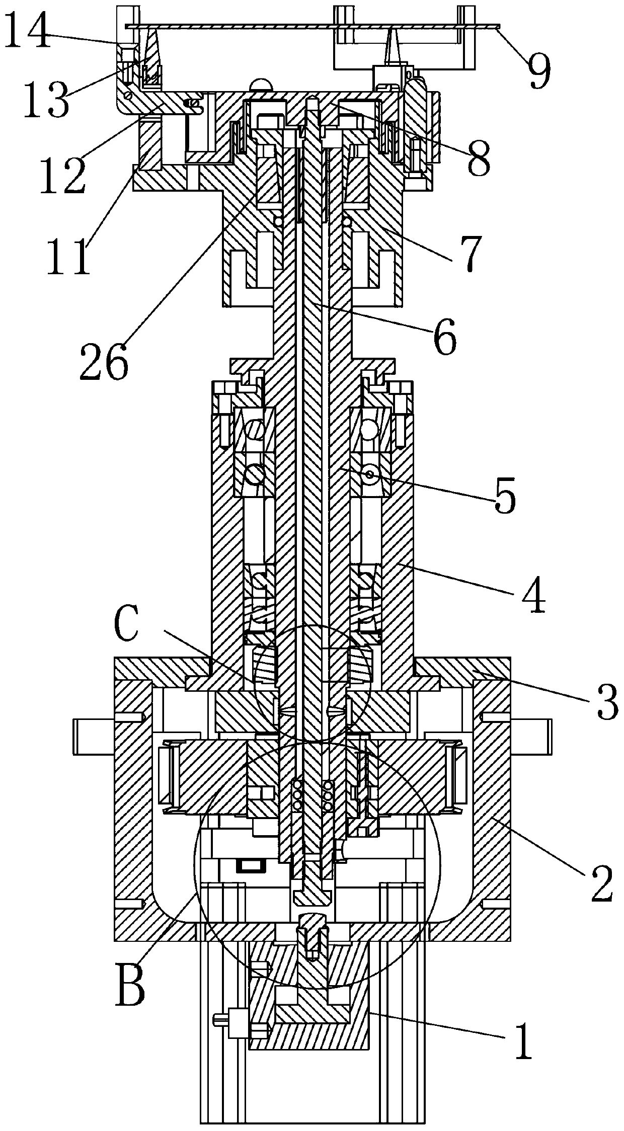
[0022] Such as image 3 As shown, a clamping spindle of a degumming machine of the present invention includes a cylinder 1, a cylinder base 2, a spindle mounting plate 3, a spindle barrel 4, a spindle 5, a ejector rod 6, a clamping sleeve 7, and a clamping lifting sleeve 8 and wafer 9; the cylinder 1 is fixed on the lower end of the cylinder base 2 with screws; the spindle mounting plate 3 is fixed on the upper end of the cylinder base 2 with screws; the spindle tube 4 is fixed on the cylinder base 2 with screws. The main shaft mounting plate 3; the main shaft 5 is rotatably arranged in the main shaft barrel 4; the main shaft 5 is provided with a first through hole 10 pen...


PUM


Abstract

The invention provides a glue removing machine clamping spindle comprising a cylinder, a cylinder seat, a spindle mounting plate, a spindle barrel, a spindle, a pushing rod, a clamping shaft sleeve, a clamping lifting sleeve and a wafer. The cylinder is fixedly installed at a lower end of the cylinder seat, the spindle mounting plate is fixedly installed at an upper end of the cylinder seat, the spindle barrel is fixedly installed on the spindle mounting plate, the spindle is rotatingly arranged in the spindle barrel, and a first through hole penetrating up and down is set in the spindle. The glue removing machine clamping spindle can realize rapid clamping or loosening, the accurate positioning of the wafer is ensured by point clamping without positional deviation, the fine adjustment of clamping force can be realized, and nitrogen gas is introduced to prevent the spindle from being damaged.

Description

technical field [0001] The invention relates to the technical field of semiconductor equipment, in particular to a clamping spindle of a glue remover. Background technique [0002] Wafer refers to the silicon wafer used in the production of silicon semiconductor integrated circuits. Because of its circular shape, it is called a wafer. The glue remover is used to remove glue from the wafer, and the spindle of the glue remover is a very critical part. The existing spindle of the glue remover is generally inaccurate when positioning the wafer, and the position is prone to shift. Contents of the invention [0003] technical problem to be solved [0004] The problem to be solved by the present invention is to provide a clamping spindle of a glue remover to overcome the defects of inaccurate positioning and prone to position deviation in the prior art. [0005] Technical solutions [0006] In order to solve the above technical problems, the present invention provides a clampi...

Claims


Application Information

Patent Timeline
Patent Type & Authority Applications(China)
IPC IPC(8): H01L21/67H01L21/687H01L21/68
CPCH01L21/67011H01L21/68H01L21/68714H01L21/68721
Inventor 傅立超魏子尧
Owner 宁波润华全芯微电子设备有限公司
Why Eureka
Try Eureka