
Display panel and display device

A display panel and thin film packaging technology, applied in diodes, semiconductor devices, electrical components, etc., can solve the problems of the display effect of the reflectivity display panel, increase the scattering of external incident light, and reduce the amount of reflected light output, so as to achieve a better display effect. Excellent, reduce direct reflection, reduce the effect of reflectivity

Active Publication Date: 2021-09-07
KUNSHAN NEW FLAT PANEL DISPLAY TECH CENT +1
View PDF5 Cites 0 Cited by
  • Summary
  • Abstract
  • Description
  • Claims
  • Application Information

AI Technical Summary

Problems solved by technology

[0005] In order to solve at least one of the problems mentioned in the background technology, the present invention provides a display panel and a display device, which effectively increase the scattering of incident light from the outside, reduce the output of reflected light, and reduce the reflectivity of ambient light. In the existing panel, the display effect of the display panel is greatly affected due to the high reflectivity of the external ambient light

Method used


Image

  • Display panel and display device
  • Display panel and display device
  • Display panel and display device

Examples


Embodiment 1

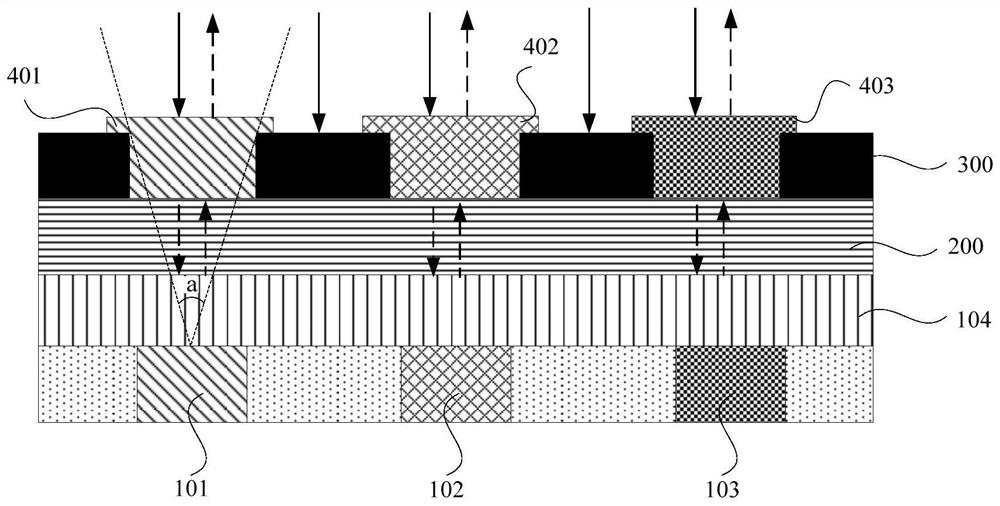
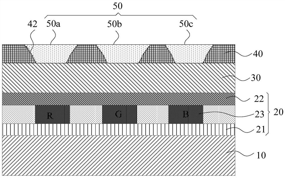
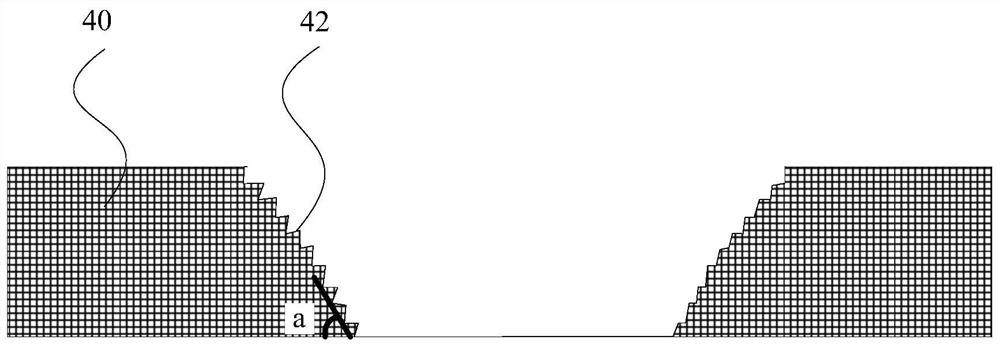
[0036] figure 2 It is a schematic cross-sectional structure diagram of a display panel provided by Embodiment 1 of the present invention, image 3 It is a schematic cross-sectional structure diagram of a part of the black matrix in the display panel provided by Embodiment 1 of the present invention, Figure 4 A schematic side view of the steps on the black matrix in the display panel provided by Embodiment 1 of the present invention, Figure 5 Another schematic cross-sectional structure diagram of the display panel provided by Embodiment 1 of the present invention, Image 6 It is a schematic cross-sectional structure diagram of an unfiltered layer in the display panel provided by Embodiment 1 of the present invention. Figure 7 It is a schematic diagram of the cross-sectional structure of the filter layer in the display panel provided by Embodiment 1 of the present invention, Image 6 It is a schematic cross-sectional structure diagram of the filter layer in the display pa...

Embodiment 2

[0058] Embodiment 2 of the present invention provides a display device. The display device can be an OLED display device and any product with a display function such as a TV, a digital camera, a mobile phone, a tablet computer, a smart watch, an e-book, a navigator, etc. that include an OLED display device or part.

[0059] Wherein, in this embodiment, the display device includes the display panel of any one of the above embodiments. In this embodiment, the structure, function and implementation of the display panel can refer to the specific description in the above embodiments, and will not be repeated here.

[0060] The display device provided by this embodiment includes the above-mentioned display panel, so that the roughness of the side of the black matrix 40 is relatively large, and the incident light is easily scattered at the step 42. Compared with the prior art, the direct reflection of the incident light is reduced. , so that the outgoing amount of reflected light is ...


PUM


Abstract

The present invention provides a display panel and a display device. The display panel includes a light emitting unit arranged on an array substrate and a thin film encapsulation layer on the light emitting unit, and also includes: a plurality of light filters arranged on the thin film encapsulation layer layer and a black matrix for separating the filter layer, wherein the side of the black matrix has a plurality of steps, and the plurality of steps are arranged obliquely outward from the bottom end to the top end of the black matrix , so that the incident light irradiated on the step is scattered. The display panel provided by the present invention effectively increases the scattering of external incident light and reduces the direct reflection of incident light, thereby reducing the outgoing amount of reflected light, further reducing the reflectivity of external ambient light, and making the display effect of the display panel Even better, it solves the problem that the display effect of the display panel is greatly affected due to the high reflectivity of external ambient light in the existing panel.

Description

technical field [0001] The present invention relates to the field of display technology, in particular to a display panel and a display device. Background technique [0002] Display screens have been widely used in many fields such as portable electronic devices (such as mobile communication terminals, tablet computers, e-books, and navigation equipment) and large-screen electronic devices. Among them, organic light-emitting diodes (Organic Light-Emitting Diode, referred to as : OLED) has been gradually applied to display screens due to its low power consumption, high color saturation, wide viewing angle, thin thickness, and flexibility. [0003] At present, in OLED displays, BM-CF technology is used to form a color filter (ColorFilter, referred to as: CF) and a black matrix (Black Matrix, referred to as: BM) on the thin film encapsulation layer to replace the circular polarizer (because the polarizer and Thick and hard), wherein, the black matrix is ​​used as a color-defin...

Claims


Application Information

Patent Timeline
Patent Type & Authority Patents(China)
IPC IPC(8): H01L27/32H01L51/52
CPCH10K59/35H10K59/38H10K59/122H10K50/8426H10K50/85H10K50/865H10K50/844
Inventor 林昶
Owner KUNSHAN NEW FLAT PANEL DISPLAY TECH CENT
Learn More