
Connector

A connector and electrical contact technology, which is applied in the direction of connection, bipolar connection, and two-component connection devices, can solve problems such as high cost, unreliable electrical contact, and reduced performance of RF coaxial connectors, so as to improve performance and reduce return. Effects of reducing wave loss and improving electrical contact reliability

Active Publication Date: 2019-09-17
TYCO ELECTRONICS (SHANGHAI) CO LTD
View PDF13 Cites 0 Cited by
  • Summary
  • Abstract
  • Description
  • Claims
  • Application Information

AI Technical Summary

Problems solved by technology

[0003] In the prior art, the contact ring at the upper end of the RF coaxial connector is a machined part, and its cost is relatively high
In addition, in the prior art, the contact ring can only make electrical contact with the upper PCB board through its circular end face, resulting in unreliable electrical contact between the two and reducing the performance of the RF coaxial connector

Method used


Image

  • Connector
  • Connector
  • Connector

Examples


Embodiment Construction

[0055] The technical solutions of the present invention will be further specifically described below through the embodiments and in conjunction with the accompanying drawings. In the specification, the same or similar reference numerals designate the same or similar components. The following description of the embodiments of the present invention with reference to the accompanying drawings is intended to explain the general inventive concept of the present invention, but should not be construed as a limitation of the present invention.

[0056] In addition, in the following detailed description, for purposes of explanation, numerous specific details are set forth in order to provide a comprehensive understanding of the embodiments of the present disclosure. It may be evident, however, that one or more embodiments may be practiced without these specific details. In other instances, well-known structures and devices are shown in diagrammatic form to simplify the drawings.

[0...


PUM


Abstract

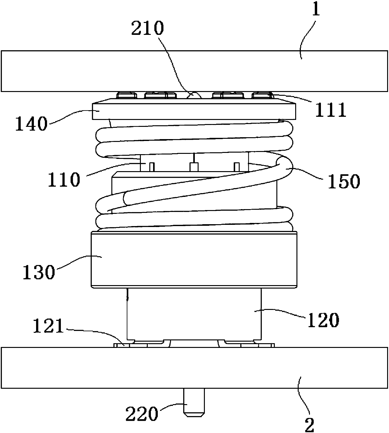
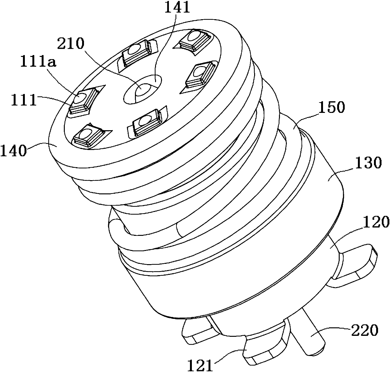
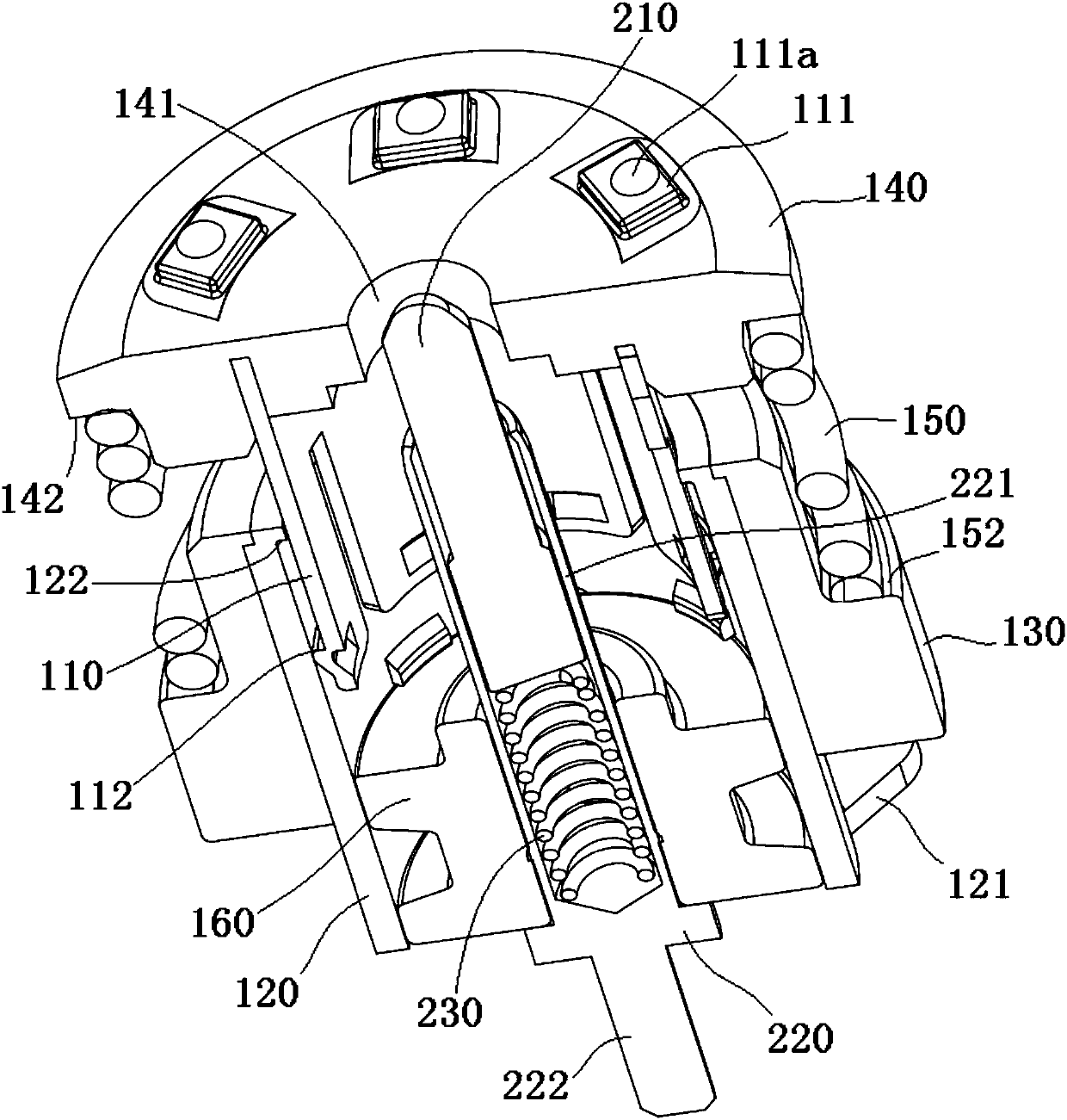
The present invention discloses a connector. The connector comprises: an external conductor comprising a first external conductor and a second external conductor which are slidingly assembled, wherein the first external conductor comprises at least one electric contact pin used for electric contact with one first electronic part; a center conductor arranged in the external conductor and comprising a first center conductor and a second conductor which are slidingly assembled; an insulation base formed on the first external conductor in an insertion molding mode, wherein the at least one electric contact pin is exposed out of the surface of the insulation base; and a first elastic element located at the outer side of the at least part of the external conductor, having one end abutted against the insulation base, being suitable for applying an axial thrust to the first external conductor to allow the electric contact pins of the first external conductor to be reliably in electric contact with the first electronic part so as to improve the electric contact performance of the connector.

Description

technical field [0001] The invention relates to a connector, in particular to a coaxial radio frequency connector. Background technique [0002] In the prior art, the lower end of the radio frequency coaxial connector of the PCB board (printed circuit board) to the PCB board is welded on a lower end PCB board, and the upper end is in electrical contact with an upper end PCB board. The outer conductor of the upper end of the RF coaxial connector is a contact ring, and the contact ring is provided with pressure by an external spring to ensure electrical contact with the upper PCB board. The outer conductor of the lower end of the RF coaxial connector is a shell, and the shell and the lower end The PCB board is soldered to ensure electrical connection with the lower PCB board. The elastic sheet is fastened between the contact ring and the housing. The lower half of the central conductor of the RF coaxial connector is welded to the lower PCB to ensure electrical connection wit...

Claims


Application Information

Patent Timeline
Patent Type & Authority Applications(China)
IPC IPC(8): H01R24/40H01R12/71H01R13/02H01R13/40
CPCH01R24/40H01R12/71H01R13/02H01R13/40H01R12/73H01R13/2421H01R13/504H01R13/6315H01R24/50H01R2103/00H01R13/2407H01R13/405H01R13/502
Inventor 倪琳宋志刚陈家辉汪云河刘松华
Owner TYCO ELECTRONICS (SHANGHAI) CO LTD
Learn More