Docking device

A technology of equipment and docking end, which is applied in the field of docking equipment, can solve the problems of increasing equipment complexity and cost, high equipment cost, and complicated positive operation, and achieve the effects of large position fault tolerance, reduced impact risk, and improved accuracy

Pending Publication Date: 2019-09-20
AMSINO MEDICAL (SHANGHAI) CO LTD
View PDF0 Cites 2 Cited by
  • Summary
  • Abstract
  • Description
  • Claims
  • Application Information

AI Technical Summary

Problems solved by technology

In the prior art, the structure that realizes the six-direction movement of the docking equipment end-to-joint needs a bracket that can move in four directions, and multiple elastic components and multiple structural components are needed to realize the modification of the bracket, and a stepping motor is added to realize the other two. Movement in one direction, complex structure, high equipment cost, and very precise alignment between the docking equipment and the waste collection equipment is required to realize the insertion of the joint, that is, the docking equipment and the waste collection equipment must be aligned before they come into contact. Only when the plug is matched with the socket can the operation be carried out, and the alignment cannot be continued after the plug touches the socket. This structure not only complicates the alignment operation, but also increases the complexity and cost of the equipment
At the same time, due to the low fault tolerance rate, under the premise of misalignment, the two joints of the docking equipment and the two joints of the waste collection equipment will cause damage to the joints

Method used


Image

  • Docking device
  • Docking device
  • Docking device

Examples


Embodiment Construction

[0042] The following descriptions of the various embodiments refer to the accompanying drawings to illustrate specific embodiments in which the present invention can be implemented. The directional terms mentioned in the present invention, such as "up", "down", "front", "back", "left", "right", "inside", "outside", "side", etc., are for reference only The orientation of the attached schema. Therefore, the directional terms used are used to illustrate and understand the present invention, but not to limit the present invention.

[0043] In order to make the purpose, technical solution and advantages of the present invention clearer, the present invention will be further described in detail below with reference to the accompanying drawings.

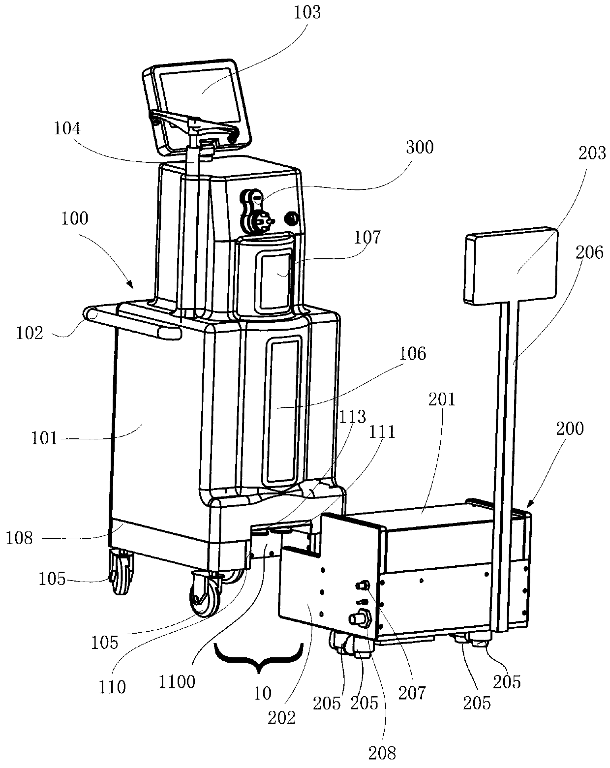
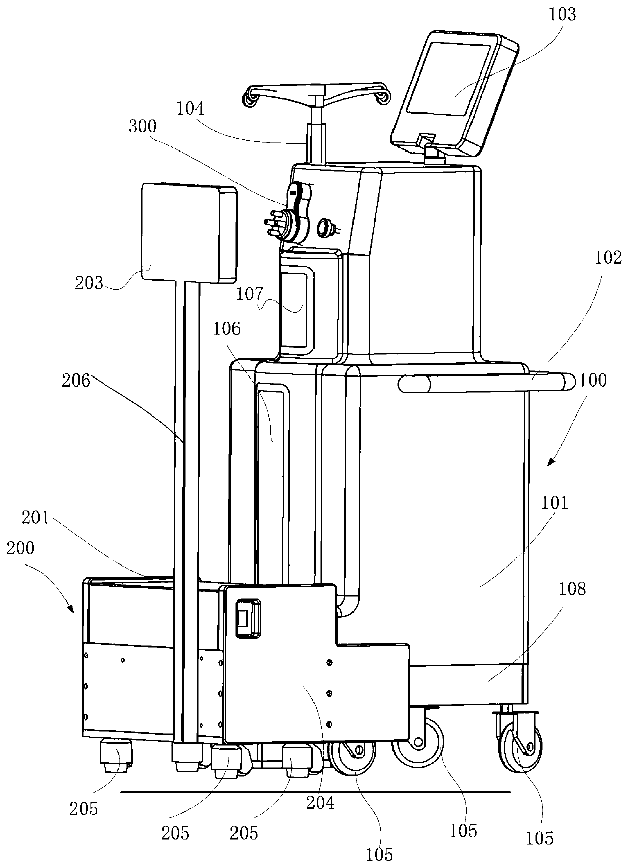
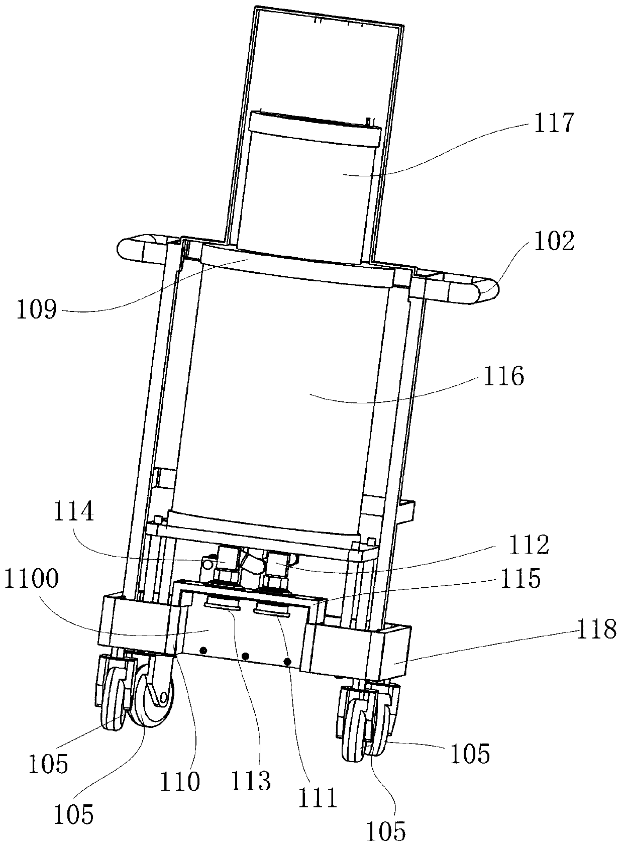
[0044] Such as Figure 1-Figure 4 as shown, figure 1 with figure 2 Shown is a waste collection and treatment system 10 comprising a waste collection device 100 and a docking device 200, figure 1 The waste collection and treatment system...


PUM


Abstract

The invention relates to a docking device, which is used in a waste collection and treatment system, and used for transporting waste generated in a medical process and collected by a waste collection device in the system. The docking device includes: a mating portion for mating with a mating bracket of the waste collection device; wherein, the mating portion includes a mating plate, and the mating plate includes two floating ferrule guiding bayonets for engaging, and a docking end joint can pass through the guiding bayonet. Wherein the docking device further includes a baffle plate, the baffle plate is in a first position when the waste collection device is not connected, and the two docking end joints are blocked; after accessing the waste collection device, the baffle plate is in a second position, and the two docking end joints are exposed to contact the floating ferrule of the waste collection device to form docking. The docking device of the embodiment of the present invention can be more easily docked with the waste collection device by an inclined surface of the mating plate.

Description

technical field [0001] The invention relates to a docking device used in a waste collection and treatment system for docking with a waste collection device that collects and processes waste materials generated in medical procedures. Background technique [0002] During the implementation of specific surgical procedures, liquid, semi-solid and solid wastes will inevitably be generated, including body fluids, such as blood, and perfusion solutions introduced into the surgical site during the surgical process. The solid and semi-solid waste generated includes tissue fragments and small pieces of surgical material that may remain on body parts. Ideally, waste is collected as it is generated so that it neither contaminates the surgical site nor becomes a biohazard in the operating room or other place where surgical procedures are performed. [0003] In the prior art, there are various waste collection and treatment systems for medical staff to collect waste generated during the ...

Claims


Application Information

Patent Timeline
Patent Type & Authority Applications(China)
IPC IPC(8): A61B90/00A61B50/37
CPCA61B50/37A61B90/00
Inventor 梁洪岐栗亚
Owner AMSINO MEDICAL (SHANGHAI) CO LTD
Why Eureka
Try Eureka