Pressure storage type fire extinguishing device and fire extinguishing method thereof

A fire extinguishing device and pressure storage technology, which is applied in fire rescue and other fields, can solve problems such as difficult to determine the state of fire extinguishers, imperfect processing algorithms, data and images without cause analysis, etc., and achieve the effect of facilitating system maintenance

Pending Publication Date: 2019-09-20
安徽安瑞德自动化科技有限公司
View PDF0 Cites 2 Cited by
  • Summary
  • Abstract
  • Description
  • Claims
  • Application Information

AI Technical Summary

Problems solved by technology

[0003] 1) Most automatic fire extinguishing devices cannot achieve multiple effective fire extinguishing during fire extinguishing;
[0004] 2) Most automatic fire extinguishing devices use linear temperature detectors, temperature detectors, smoke detectors, etc. with poor detection sensitivity
A small number of single-ultraviolet detectors are used as the detection unit, which cannot resist the interference of various light sources such as strong light, weak light, and flash lights in the environment during actual use, and the processing algorithm is not perfect, which makes it easy to appear automatic fire extinguishing devices during use Malfunction;
[0005] 3) Most of the automatic fire extinguishing devices have no fault self-diagnosis function, which leads to failure to find and deal with them in time after the parts of the automatic fire extinguishing device have problems;
[000

Method used


Image

  • Pressure storage type fire extinguishing device and fire extinguishing method thereof
  • Pressure storage type fire extinguishing device and fire extinguishing method thereof
  • Pressure storage type fire extinguishing device and fire extinguishing method thereof

Examples


Example Embodiment

[0032] The embodiments of the present invention are described in detail below. Examples of the embodiments are shown in the accompanying drawings, in which the same or similar reference numerals indicate the same or similar elements or elements with the same or similar functions. The embodiments described below with reference to the accompanying drawings are exemplary, and are intended to explain the present invention, but should not be construed as limiting the present invention. In the description of the present invention, it needs to be understood that the orientation or positional relationship indicated by the terms "upper", "lower", "front", "rear", etc. is based on the orientation or positional relationship shown in the drawings, and is only for It is convenient to describe the present invention and simplify the description, instead of indicating or implying that the device or element referred to must have a specific orientation, be constructed and operated in a specific o...


PUM


Abstract

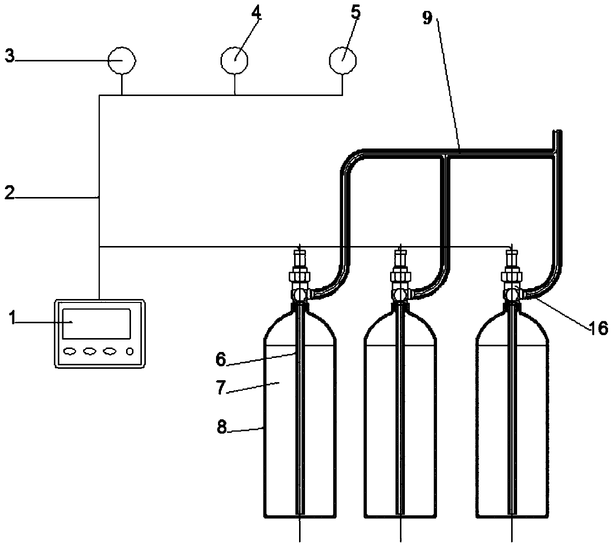
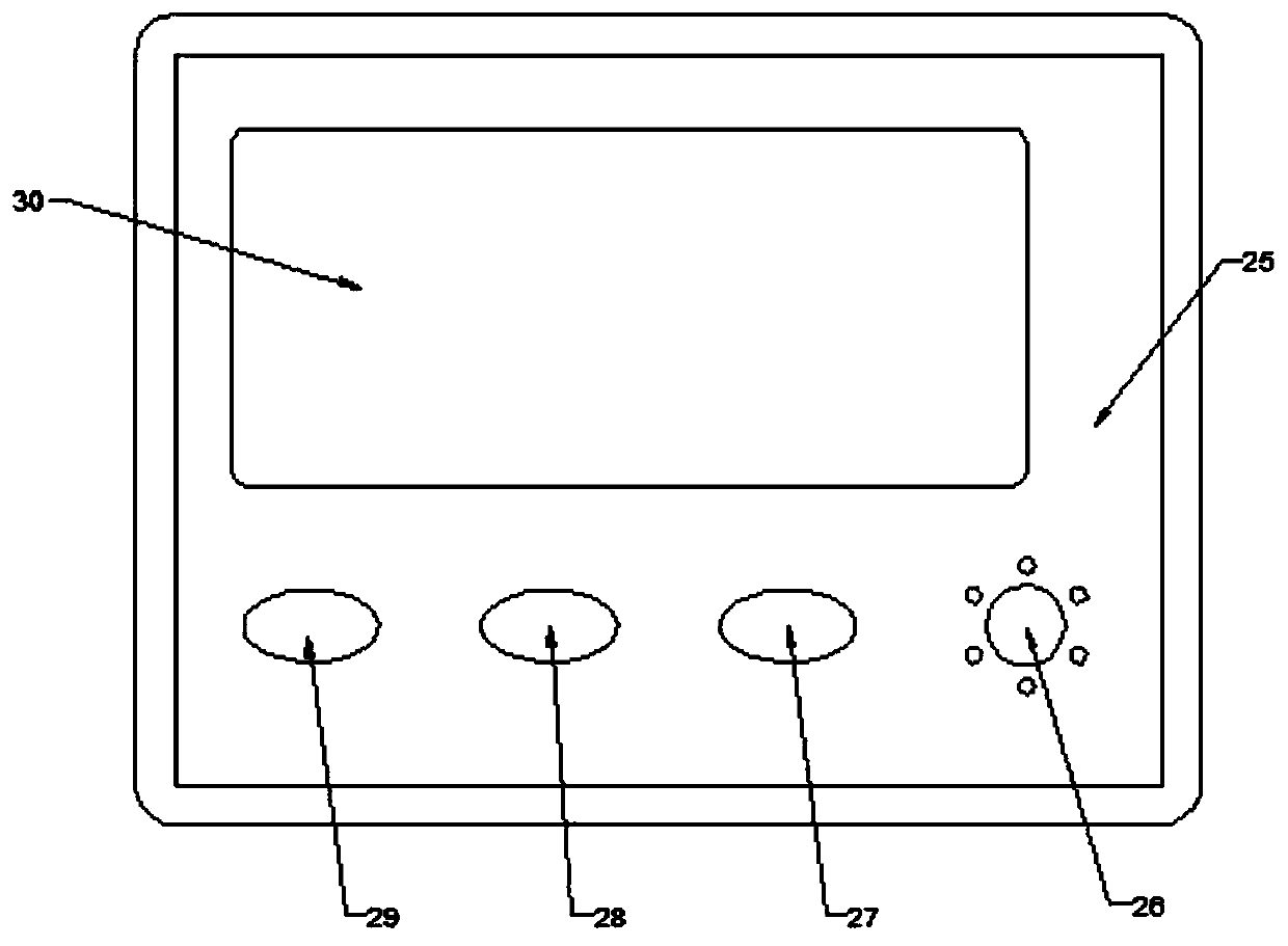
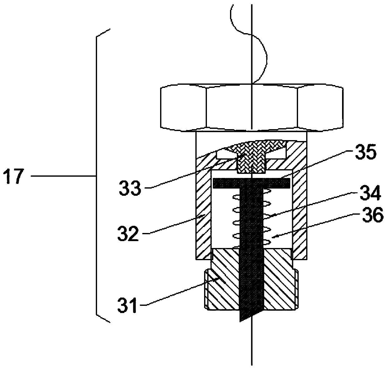
The invention discloses a pressure storage type fire extinguishing device. The fire extinguishing device comprises fire extinguishing bottles, electrical explosion devices, valve bodies, siphons, fire extinguishing pipelines, a control terminal, a cable assembly, a flame detector, an infrared thermal imaging detector and a temperature and pressure detector, and fire extinguishing agents are stored in the fire extinguishing bottles; the electrical explosion devices are connected with the valve bodies through threads; the valve bodies are connected with the fire extinguishing bottles through threads, and tank body sealing is achieved; nitrogen or air is stored in sealed cavities formed by the fire extinguishing agents, the fire extinguishing bottles, the siphons and the valve bodies; a pressure gauge is installed on one side of each diaphragm sealing type valve body; the valve bodies are connected with the siphons through threads and connected with the fire extinguishing pipelines; and the control terminal is provided with the infrared thermal imaging detector, the temperature and pressure detector and the flame detector. By cooperating with a fire extinguishing method, the device not only has the advantages of being convenient and fast to operate, safe, efficient and the like, but also can achieve multiple times of effective fire extinguishing.

Description

technical field [0001] The invention relates to the technical field of fire protection, in particular to a pressure storage type fire extinguishing device and a fire extinguishing method thereof. Background technique [0002] At present, domestic automatic fire extinguishing devices are still in their infancy, and there are many problems: [0003] 1) Most automatic fire extinguishing devices cannot achieve multiple effective fire extinguishing during fire extinguishing; [0004] 2) Most of the automatic fire extinguishing devices use line type temperature detectors, temperature detectors, smoke detectors and other detection sensitivities. A small number of single-ultraviolet detectors are used as the detection unit, which cannot resist the interference of various light sources such as strong light, weak light, and flash lights in the environment during actual use, and the processing algorithm is not perfect, which makes it easy to appear automatic fire extinguishing devices...

Claims


Application Information

Patent Timeline
IPC IPC(8): A62C31/00A62C37/40
CPCA62C31/00A62C37/40
Inventor 许同刚吴鸿雁程亚栋杨素
Owner 安徽安瑞德自动化科技有限公司
Why Eureka
Try Eureka