Oil filtering system and method

A filtration system and oil technology, applied in the direction of filtration separation, separation method, gravity filter, etc., can solve the problems of poor filtration effect and singleness, and achieve the effect of speeding up discharge, ensuring filtration efficiency and improving filtration effect.

Pending Publication Date: 2019-09-20
浙江安贝实业有限公司
View PDF6 Cites 4 Cited by
  • Summary
  • Abstract
  • Description
  • Claims
  • Application Information

AI Technical Summary

Problems solved by technology

[0002] Grease refers to the general term for oil and fat. It is used in various fields, such as: industrial lubricating oil, referred to as: lubricating oil; lubricating oil is used in various types of automobiles and mechanical equipment to reduce friction and protect machinery and equipment. The liquid or semi-solid lubricant of the workpiece mainly plays the role of lubrication, cooling, rust prevention, cleaning, sealing and buffering; the lubricating oil needs to be filtered before the lubricating oil is used, and the existing filtering methods and equipment are relatively simple. There are a series of defects such as poor filtering effect (including filtering efficiency)

Method used


Image

  • Oil filtering system and method
  • Oil filtering system and method
  • Oil filtering system and method

Examples


Embodiment 1

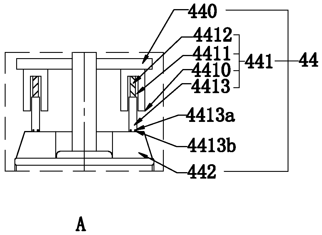
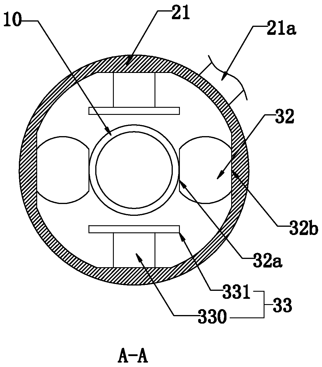
[0030] Such as Figure 1 to Figure 6 As shown, the present invention discloses a grease filtering system, including a frame 1, in a specific embodiment of the present invention, including a preheating assembly 2 installed on the frame 1 and used to place a lubricating oil storage tank 10, partly located The extruding assembly 3 inside the preheating assembly 2 is used to squeeze the outer wall of the lubricating oil storage tank 10 from bottom to top, and the feeding assembly 4 is driven up and down by the cylinder 11 and is located directly above the preheating assembly 2 and is used to extract lubricating oil. And a filter assembly 5 communicating with the feeding assembly 4 and used for receiving lubricating oil and filtering it.

[0031]In a specific embodiment of the present invention, the preheating assembly 2 includes a preheating cylinder 21 fixedly connected to the frame 1 and having a storage chamber 20, fixedly connected to the inner wall of the preheating cylinder ...

Embodiment 2

[0056] A method for filtering grease as claimed in the preceding claims, comprising the steps of:

[0057] S1 storage tank installation: Open the tank cover on the top of the storage tank with lubricating oil in advance and put it into the preheating cylinder, lift the support platform through the cylinder so that one end of the oil inlet pipe penetrates into the storage tank from the top of the storage tank and stops. And through the limit module set on the oil inlet pipe to contact with the top of the storage tank, the installation is completed;;

[0058] S2 Pre-heating treatment: Add an appropriate amount of water into the pre-heating cylinder, and then heat it through the above-mentioned electromagnetic heater, keep the water temperature at 75°C, and start pumping the lubricating oil after 15 minutes of pre-heating time;

[0059] S3 Drain and squeeze: Drain all the water in the preheating cylinder, drive the extrusion module through the hydraulic cylinder to squeeze the ou...


PUM


Abstract

The invention relates to an oil filtering system and method. The oil filtering system comprises a frame and is characterized by comprising a preheating module mounted on the frame for placing a lubricating oil storage tank, an extruding module partly arranged inside the preheating module for pressing the outer wall of the lubricating oil storage tank from bottom to top, a feeding module at least driven by an air cylinder to move and down and arranged right above the preheating module for sucking lubricating oil, and a filtering module communicated with the feeding module for receiving and filtering the lubricating oil. The oil filtering method comprises S1, storage tank installation, S2, preheating treatment, S3, water draining extrusion and S4, repeated extrusion. The oil filtering system and method has the advantages of being good in filtering effects and high in filtering efficiency.

Description

technical field [0001] The invention relates to the technical field of grease filtration, in particular to a grease filtration system and a filtration method thereof. Background technique [0002] Grease refers to the general term for oil and fat. It is used in various fields, such as: industrial lubricating oil, referred to as: lubricating oil; lubricating oil is used in various types of automobiles and mechanical equipment to reduce friction and protect machinery and equipment. The liquid or semi-solid lubricant of the workpiece mainly plays the role of lubrication, cooling, rust prevention, cleaning, sealing and buffering; the lubricating oil needs to be filtered before the lubricating oil is used, and the existing filtering methods and equipment are relatively simple. There are a series of defects such as poor filtering effect (including filtering efficiency). Contents of the invention [0003] Aiming at the deficiencies in the prior art, the object of the present inv...

Claims


Application Information

Patent Timeline
Patent Type & Authority Applications(China)
IPC IPC(8): B01D29/03B01D29/31B01D29/50B01D29/90C10M175/00
CPCB01D29/03B01D29/31B01D29/50B01D29/90C10M175/0083
Inventor 曹金明周建水夏敏曹新伟
Owner 浙江安贝实业有限公司
Why Eureka
Try Eureka