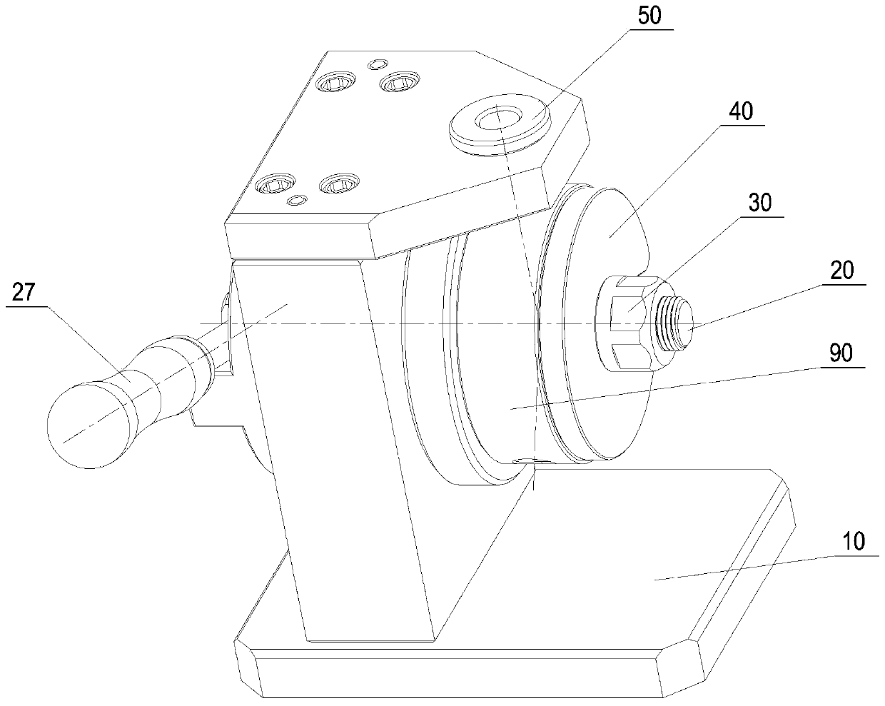
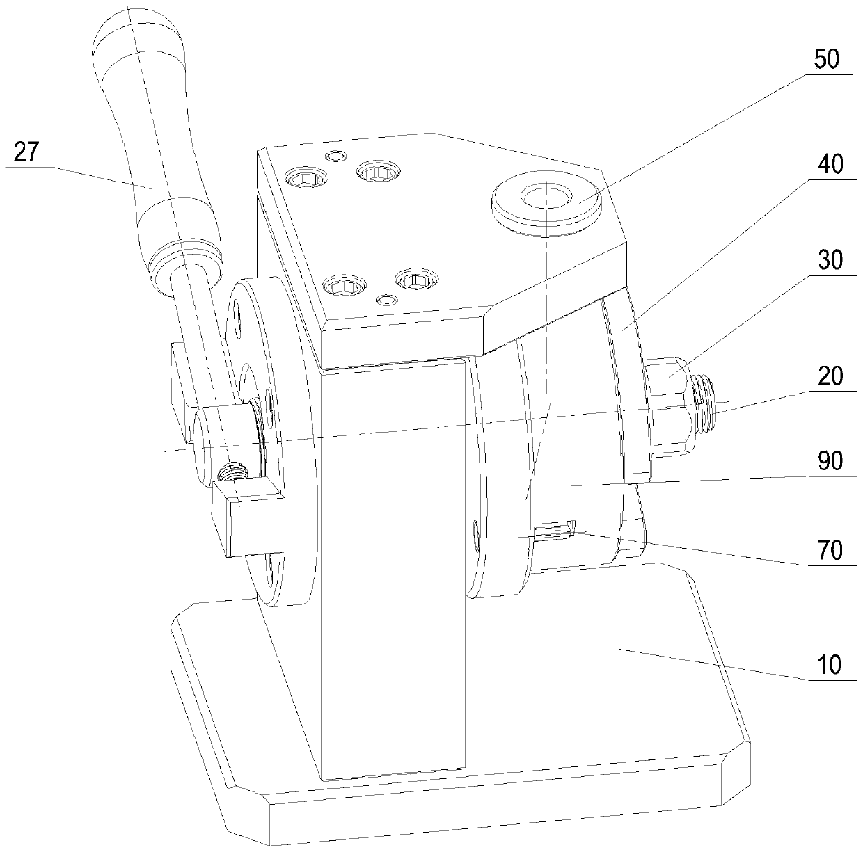
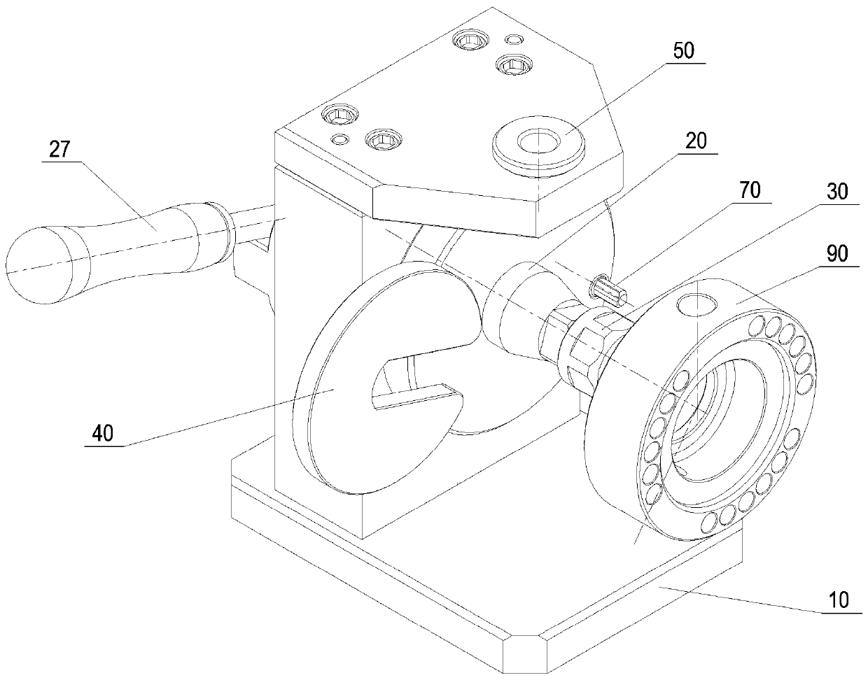
Rotary shaft type drilling tool
A drilling tool and shaft technology, which is applied in boring/drilling, drilling/drilling equipment, positioning devices, etc., can solve the problems of high precision requirements and many processing procedures, and achieve compact and simple structure, reverse drilling The effect of convenience and convenient loading and unloading of workpieces
- Summary
- Abstract
- Description
- Claims
- Application Information
AI Technical Summary
Problems solved by technology
Method used
Image

Examples
Embodiment Construction
[0017] The technical solutions of the present invention will be described in detail below, but the protection scope of the present invention is not limited to the embodiments.
[0018] In order to make the content of the present invention more obvious and understandable, the following in conjunction with the attached Figure 1-Figure 6 and specific implementation methods for further description.
[0019] In order to make the object, technical solution and advantages of the present invention clearer, the present invention will be further described in detail below in conjunction with the accompanying drawings and embodiments. It should be understood that the specific embodiments described here are only used to explain the present invention, not to limit the present invention.
[0020] Such as Figure 6 As shown, rock drilling equipment is used to break soft ore, demolish solid or cement buildings, mine clay, etc., and the rock drilling equipment is mainly pneumatic rock drills...
PUM
 Abstract
Description
Claims
Application Information
PatSnap Eureka turns technology decisions into work you can execute. Powered by our Innovation Knowledge Graph, it runs expert workflows across engineering, life sciences, materials and intellectual property. Get your review-ready output in minutes.


