Foam rotary forming machine

A molding machine and foam technology, used in household components, household appliances, other household appliances, etc., can solve the problems of high consumption of materials, low market acceptance rate, and high production cost, and can solve the problems of large land area, increased market acceptance rate, Crafting the effect of reduced difficulty

Pending Publication Date: 2019-09-20
广州市裕航电气机械有限公司
View PDF0 Cites 2 Cited by
  • Summary
  • Abstract
  • Description
  • Claims
  • Application Information

AI Technical Summary

Problems solved by technology

At this time, most of them enter the machine manually, put the shell into the mold, and carry out production. The production efficiency is low; One of the fixed molds and the movable mold are in production, and the other fixed mold is given to manually install the mold
[0003] However, the left and right mold shifting machines are huge, and the land area needed to move the mold is large, resulting in a low space utilization rate in the production workshop. Because of the huge machine, the production difficulty is high, and a lot of materials are consumed, the production cost of the machine is too high. High, low market recognition rate
And because it is necessary to keep one of the fixed mold and the movable mold in production, and the other fixed mold must be manually installed, so the production efficiency of the special structure under this process is obviously not high.

Method used


Image

  • Foam rotary forming machine
  • Foam rotary forming machine
  • Foam rotary forming machine

Examples


Embodiment Construction

[0023] In order to better illustrate the principle and structure of the technical solution of the present invention, one embodiment of the present invention will be described below in conjunction with the contents of the accompanying drawings.

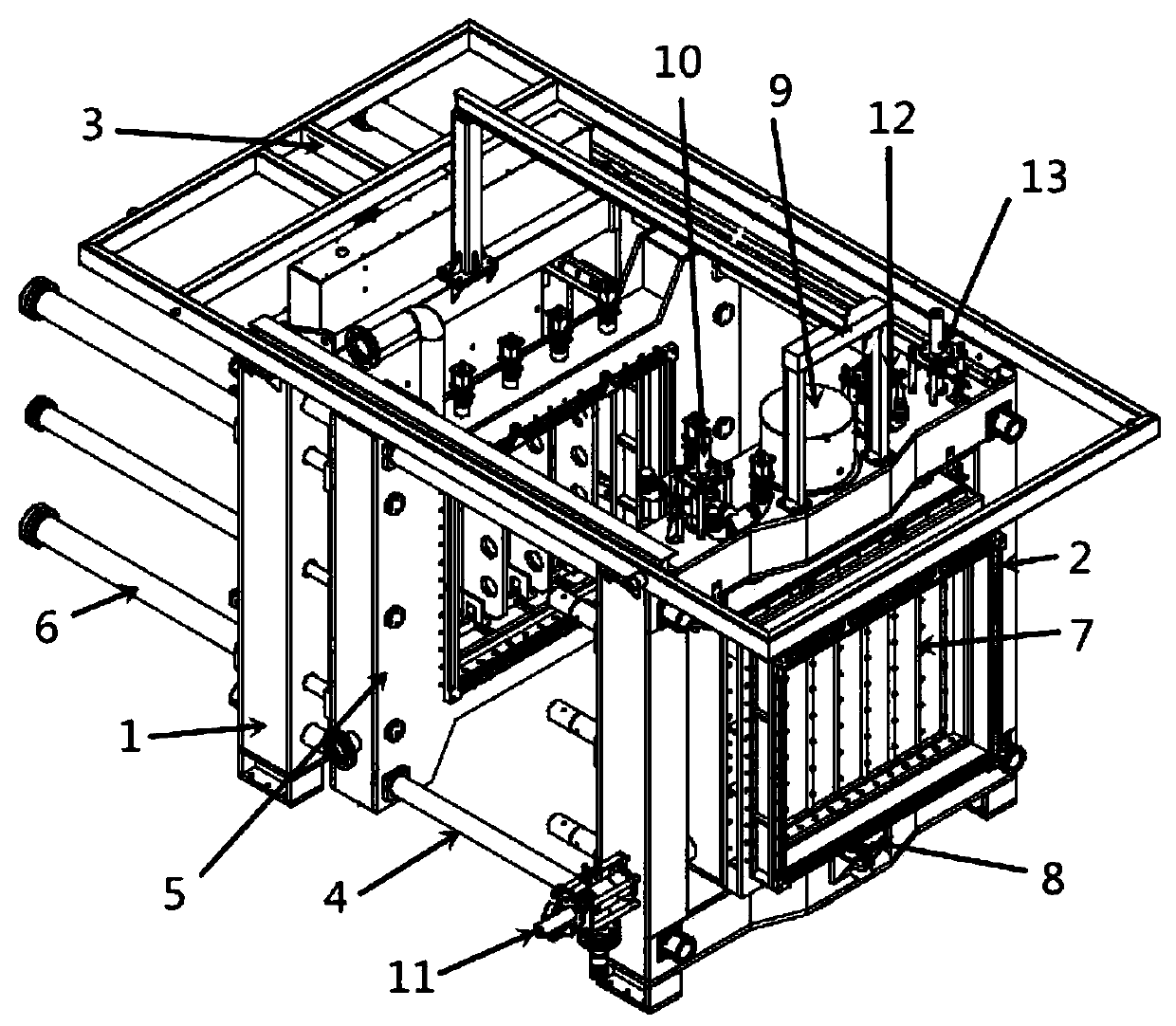
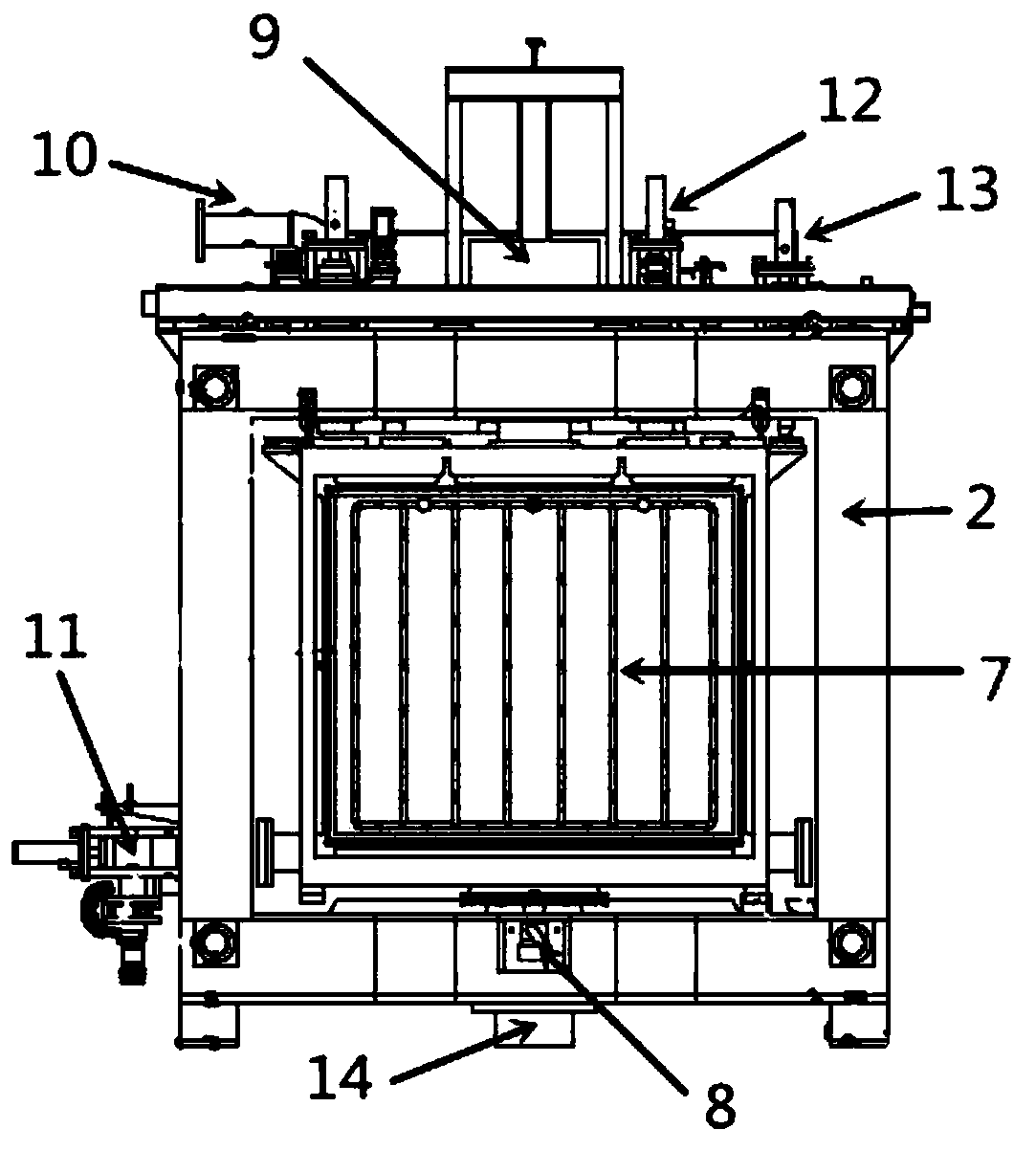
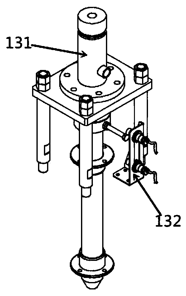
[0024] like Figure 1 to Figure 6 As shown, the foam rotary molding machine of this embodiment includes a rear frame 1, a front frame 2, a fixed frame 3, a guide rod 4, a movable mold machine 5, a movable mold push rod 6, and a double-chamber water tank 7 , water tank motor 8, rotary encoder 9, enter steam telescopic mechanism 10, drainage telescopic mechanism 11, enter water telescopic mechanism 12, fine positioning mechanism 13, rotating main shaft 14. Among them, the steam inlet telescopic mechanism 10 includes a steam push rod 101, a steam switch 102, an inner tooth elbow 103, a diffuser valve 104, an outer tooth straight-through 105, a tee 106, and an undercut 107; the drainage telescopic mechanism 11 includes a drainage push Rod...


PUM


Abstract

The invention discloses a foam rotary forming machine and belongs to the technical field of foam forming machining equipment. The foam rotary forming machine comprises a rack, a movable mold machine, a rotatable water tank assembly, an additionally designed water inlet and outlet mechanism and a steam mechanism. As for the rotatable water tank assembly, the movable mold machine and the rack, under the cooperation of the additionally designed water inlet and outlet mechanism and the steam mechanism, the movement of the rotatable water tank assembly and the movable mold machine according to technological requirements is achieved. By the adoption of the foam rotary forming machine, the defect that an existing machine is too large and occupies production space in the process of heating and forming foam can be avoided, meanwhile, a process of synchronously filling a foam sheet and forming and heating is adopted, and high-efficiency production of products is realized.

Description

technical field [0001] The invention belongs to the technical field of foam molding processing equipment, in particular to equipment for foam molding processing. Background technique [0002] At present, in the EPS / EPP foam molding industry, some products with high production requirements need to mold the shell and foam at one time during foam molding. Therefore, during production, the shell needs to be embedded in the mold in advance, and then filled with foam Foaming is carried out to directly produce semi-finished / finished products with shells. At this time, most of them enter the machine manually, put the shell into the mold, and carry out production. The production efficiency is low; One of the fixed molds and the movable mold are in production, and the other fixed mold is manually installed. [0003] However, the left and right mold shifting machines are huge, and the land area needed to move the mold is large, resulting in a low space utilization rate in the product...

Claims


Application Information

Patent Timeline
Patent Type & Authority Applications(China)
IPC IPC(8): B29C44/12B29C44/34B29L31/48
CPCB29C44/1219B29C44/3426B29L2031/4821
Inventor 梁灿贤
Owner 广州市裕航电气机械有限公司
Why Eureka
Try Eureka