
A bearing ring revolving frame

A technology of turnover frame and bearing ring, applied in the field of bearings, can solve the problems of scattered bearing rings, reduced production efficiency, inconvenient turnover, etc.

Active Publication Date: 2020-07-31
安徽华旦机械制造有限公司
View PDF6 Cites 0 Cited by
  • Summary
  • Abstract
  • Description
  • Claims
  • Application Information

AI Technical Summary

Problems solved by technology

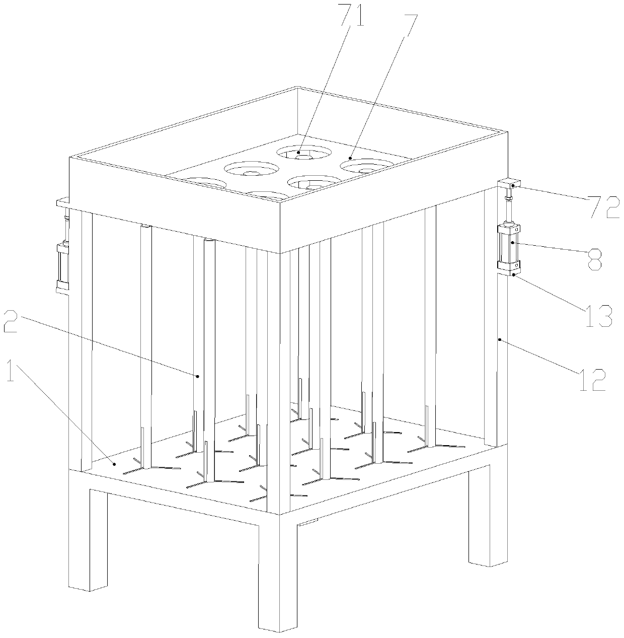
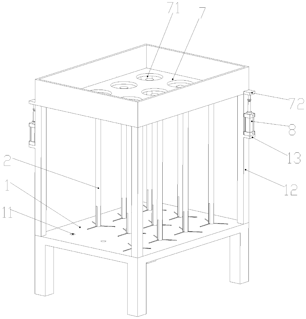
In the production of bearings, it is often necessary to turn over the processed bearing rings, but the produced bearing rings are scattered after they come out, which is inconvenient to turn over, resulting in a decrease in production efficiency

Method used


Image

  • A bearing ring revolving frame
  • A bearing ring revolving frame
  • A bearing ring revolving frame

Examples


Embodiment Construction

[0032] The following will clearly and completely describe the technical solutions in the embodiments of the present invention with reference to the accompanying drawings in the embodiments of the present invention. Obviously, the described embodiments are only some, not all, embodiments of the present invention. Based on the embodiments of the present invention, all other embodiments obtained by persons of ordinary skill in the art without creative efforts fall within the protection scope of the present invention.

[0033] In describing the present invention, it is to be understood that the terms "opening", "upper", "lower", "thickness", "top", "middle", "length", "inner", "surrounding" etc. Indicating orientation or positional relationship is only for the convenience of describing the present invention and simplifying the description, and does not indicate or imply that the components or elements referred to must have a specific orientation, be constructed and operated in a sp...


PUM


Abstract

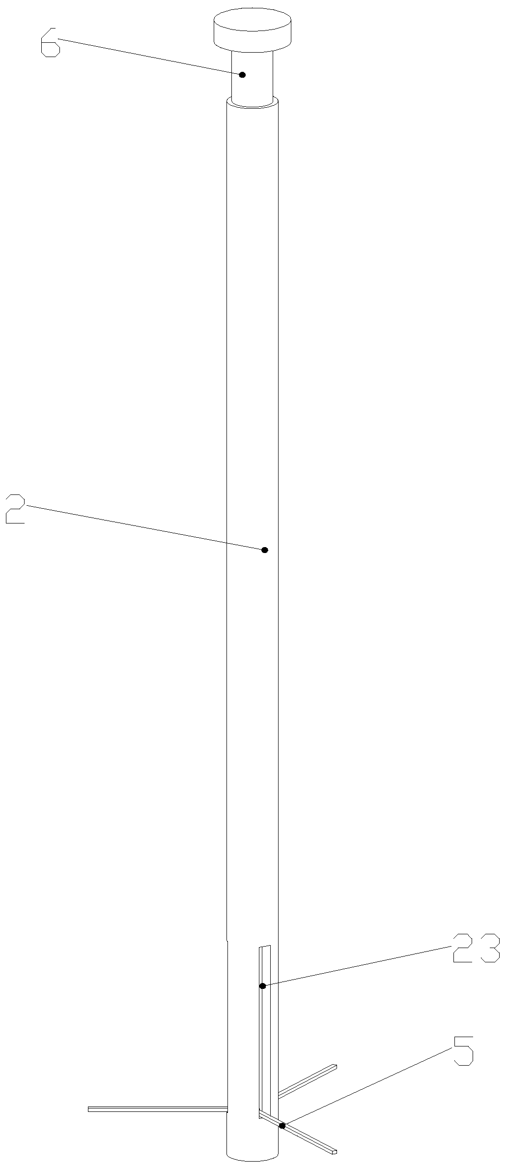
The invention discloses a bearing race turnover frame. The bearing race turnover frame comprises a placement table, wherein mounting holes are formed in the upper end of the placement table; turnover frame bodies are inserted into the mounting holes; a first round hole is formed in the upper end of each turnover frame body; a second round hole is formed in each first round hole; a take-up groove is formed in the lower end part of each turnover frame body; a threaded pipe sleeve is placed in each first round hole; an annular groove is formed in each threaded pipe sleeve; an annular limit key is arranged at the upper end of each turnover frame body; a threaded rod is mounted in each threaded pipe sleeve; a rectangular groove is formed in a side wall at the lower end of each threaded rod; a rotating shaft is arranged in each rectangular groove; a support bar is arranged on each rotating shaft. Machined bearing races are placed in a collection box, at this time, the bearing races fall onto the turnover frame bodies, and the turnover frame bodies string the bearing races together and regularly arrange the bearing races. After the turnover frame bodies and the bearing races on the turnover frame bodies are carried to a target area, the threaded rods are moved upwards. At this time, the support bars roll up, the bearing races that are arranged on the turnover frame bodies in a sleeving manner are separated from the turnover frame bodies and regularly placed on the target area.

Description

technical field [0001] The invention relates to the field of bearings, in particular to a bearing ring turnover frame. Background technique [0002] Bearing is an important part of contemporary mechanical equipment. Its main function is to support the mechanical rotating body, reduce the friction coefficient during its movement, and ensure its rotation accuracy. According to the different friction properties of moving elements, bearings can be divided into two categories: rolling bearings and sliding bearings. Among them, the rolling bearing has been standardized and serialized, but compared with the sliding bearing, its radial dimension, vibration and noise are larger, and the price is also higher. Rolling bearings are generally composed of four parts: outer ring, inner ring, rolling elements and cage. According to the shape of rolling elements, rolling bearings are divided into two categories: ball bearings and roller bearings. In the production of bearings, it is ofte...

Claims


Application Information

Patent Timeline
Patent Type & Authority Patents(China)
IPC IPC(8): B65D6/08B65D85/58
CPCB65D7/14B65D11/14B65D85/58
Inventor 金礼文勤
Owner 安徽华旦机械制造有限公司
Learn More