
Fabricating structure and method of prefabricated component

A technology of prefabricated components and assembly methods, which is applied in the direction of structural elements, building components, building reinforcements, etc., can solve the problems of long preparation time period, scaffolding occupying the construction site, and prolonging the construction period, so as to shorten the construction period and simplify the assembly method , Improve the effect of connection strength

Pending Publication Date: 2019-09-20
李藏柱
View PDF0 Cites 2 Cited by
  • Summary
  • Abstract
  • Description
  • Claims
  • Application Information

AI Technical Summary

Problems solved by technology

[0003] The above process has the following defects. First, the preparatory work period is long; the construction site is occupied by scaffolding; secondly, during the construction process, the length of the steel bar is relatively large, and the hoisting of the steel bar on site requires the investment of mechanical equipment; there are certain safety hazards in the hoisting process
[0004] Finally, after the steel frame binding is completed, the construction site needs to be cleaned up to extend the construction period

Method used


Image

  • Fabricating structure and method of prefabricated component
  • Fabricating structure and method of prefabricated component
  • Fabricating structure and method of prefabricated component

Examples


Embodiment 1

[0072] A method for assembling prefabricated components 2, comprising the steps of:

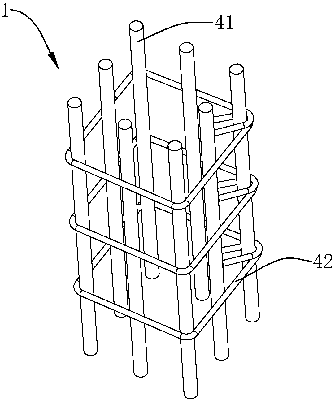
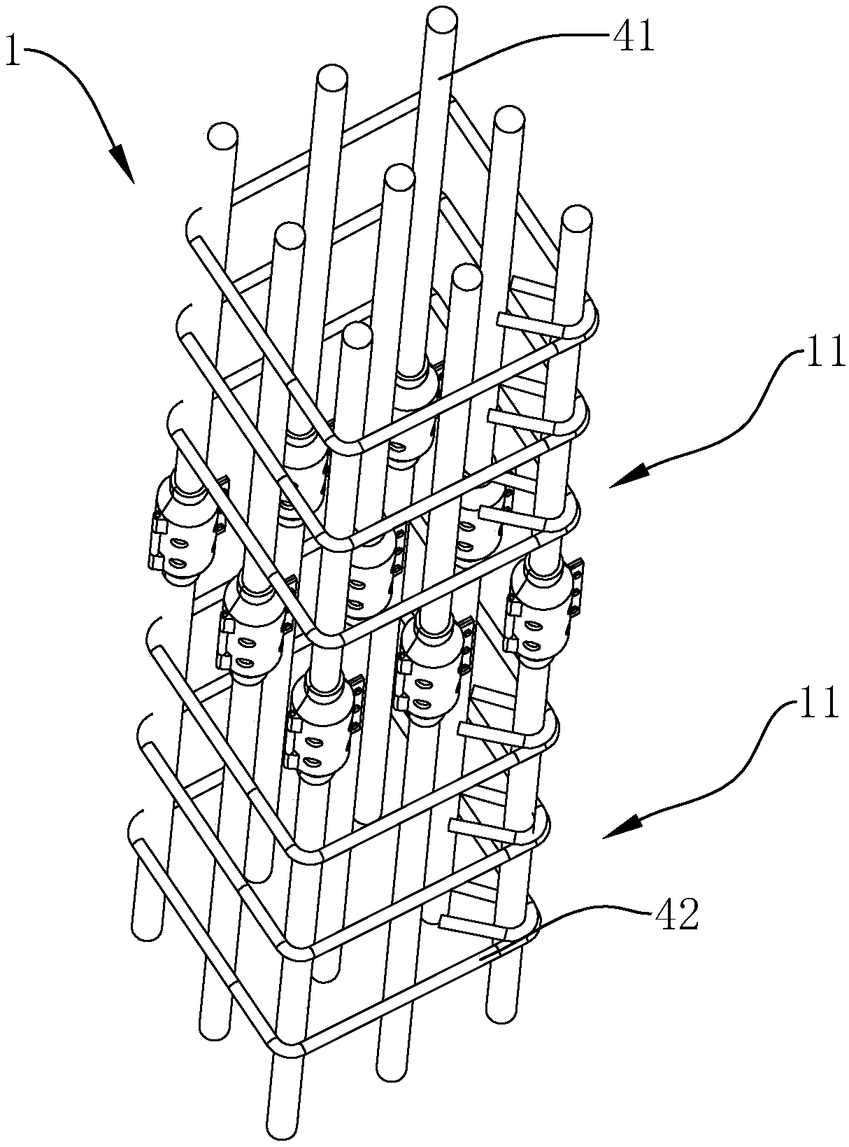
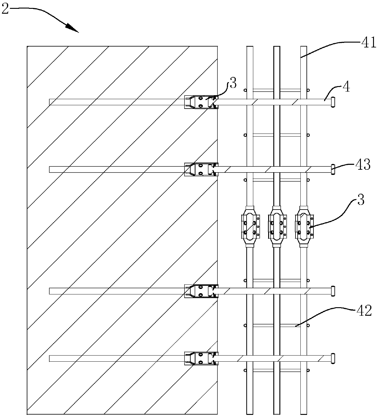
[0073] S1, see figure 1 with figure 2 , compiling the reinforcement skeleton 1 and preparing the prefabricated component 2, the end face of the prefabricated component 2 is pre-embedded with a plurality of sleeves 3 during the prefabrication process, and the opening at one end of the sleeve 3 is located on the plane where the end face is located;

[0074] S2, see image 3 , the end face of the prefabricated component 2 is set facing the reinforcement frame 1, the sleeve 3 of the reinforcement frame 1 corresponding to the end face of the prefabricated component 2 crosses the reinforcement bar 4, and the reinforcement bar 4 passes through the reinforcement frame 1;

[0075] S3, see Figure 4 Push the prefabricated component 2 to abut against the reinforcement frame 1, and insert the end of the reinforcement bar 4 that crosses the reinforcement frame 1 into the sleeve 3;

[0076] S4 , grout...

Embodiment 2

[0089] Embodiment two: the difference with embodiment one is that in the above steps, the reinforcement frame 1 is a circular reinforcement frame 12 in the section surrounded by several longitudinal bars 41, and the outer side of the reinforcement frame 1 is provided with circular stirrups 42, and the longitudinal bars 41 and stirrups 42 constitute the cylindrical reinforcement skeleton 1.

[0090] The prefabricated component 2 is a rectangular prefabricated slab 21. The end surface of the prefabricated slab 21 faces the arc surface of the steel frame 1 that matches the cylindrical steel frame 1. A sleeve 3 is pre-embedded on the arc surface, and the sleeve 3 is far away from the prefabricated slab 21. Elastic slips 32 are provided at one end.

[0091] The assembly form of the assembly formed by the above steps can be found in Figure 7 with Figure 8 , can be two prefabricated panels 21, each prefabricated panel 21 has a semicircular end face facing the cylindrical steel fr...


PUM


Abstract

The invention discloses a fabricating structure and method of a prefabricated component, and belongs to the field of fabricated buildings. According to the fabricating method, prefabricated plates and rebar concrete are fixedly fabricated into the unified whole through rebar sleeves and concrete. Through stress cooperation generated among the sleeve, the concrete and rebars, the connecting strength of the finally-formed fabricating structure is greatly enhanced, the prefabricated component fabricated through the method is easy to assembly during construction, the prefabricated plates can be quickly fabricated, and the construction period is greatly shortened.

Description

technical field [0001] The invention relates to the field of prefabricated buildings, in particular to an assembly structure and an assembly method of prefabricated components. Background technique [0002] At present, the steel skeleton of the prefabricated building is mainly bound on site according to the height of the construction, and then assembled with the prefabricated frame. The construction process of on-site lashing includes setting up scaffolding, laying springboards around the operation surface and hanging safety nets. [0003] The above process has the following defects. First, the preparatory work period is long; the scaffolding takes up the construction site; secondly, during the construction process, the length of the steel bar is relatively large, and the hoisting of the steel bar on site requires the investment of mechanical equipment; there are certain safety hazards in the hoisting process. [0004] Finally, after the steel frame binding is completed, th...

Claims


Application Information

Patent Timeline
IPC IPC(8): E04B1/00E04C2/00E04C5/06E04C5/16
CPCE04B1/00E04C2/00E04C5/06E04C5/162
Inventor 李藏柱
Owner 李藏柱
Learn More