Supercharge Your Innovation With Domain-Expert AI Agents!

Fabricated beam, fabricated double-spliced T-shaped beam and construction method of fabricated double-spliced T-shaped beam

A prefabricated, integrated technology that can be used in building types, protected buildings/shelters, building components, etc., and can solve problems such as unconsidered

Active Publication Date: 2019-09-20
建邦技术集团有限公司
View PDF11 Cites 0 Cited by
  • Summary
  • Abstract
  • Description
  • Claims
  • Application Information

AI Technical Summary

Problems solved by technology

[0005] However, in today's design, both, especially how to improve the firmness of the connection between concrete beams and rack plates, are not considered

Method used


Image

  • Fabricated beam, fabricated double-spliced T-shaped beam and construction method of fabricated double-spliced T-shaped beam
  • Fabricated beam, fabricated double-spliced T-shaped beam and construction method of fabricated double-spliced T-shaped beam
  • Fabricated beam, fabricated double-spliced T-shaped beam and construction method of fabricated double-spliced T-shaped beam

Examples


Embodiment 1

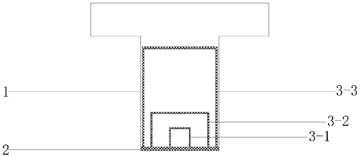
[0046] Embodiment one, such as figure 1 As shown, a prefabricated beam includes a concrete body 1 and a force transmission plate 2;

[0047] The force transmission plate 2 is arranged on the lower surface of the beam, which is used as the formwork of the concrete body; the first C-shaped plate 3-1, the second C-shaped plate 3-2, and the third C-shaped plate 3 are arranged on the upper part of the force transmission plate -3;

[0048] The opening of the first C-shaped plate 3-1 is downward and connected with the force transmission plate 2;

[0049] The opening of the second C-shaped plate 3-2 is downward and connected with the force transmission plate 2;

[0050] The opening of the third C-shaped plate 3-3 is downward and connected with the force transmission plate 2;

[0051]The third C-shaped plate 3-3 wraps the second C-shaped plate 3-2 inside, and the second C-shaped plate wraps the first C-shaped plate 3-1 inside.

[0052] How to avoid slipping between the force trans...

Embodiment 2

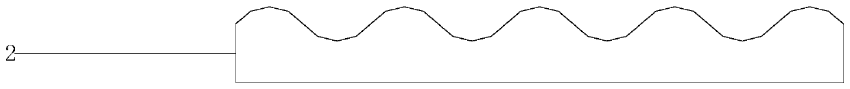
[0053] Embodiment two, in order to further improve the anti-slip effect, such as figure 2 As shown, the upper surface of the force transmission plate is set to be wavy, and it is wavy along the forward direction of the beam; the lower surface of the force transmission plate is provided with racks according to actual needs;

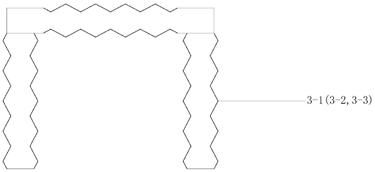
[0054] like image 3 As shown, the inner and outer surfaces of the first C-shaped plate 3-1 are all wave-shaped, the wave shape of the vertical plate of the first C-shaped plate is distributed along the vertical direction, and the wave shape of the horizontal plate of the first C-shaped plate The shape is distributed along the width direction of the beam;

[0055] The inner and outer surfaces of the second C-shaped plate 3-2 are all wave-shaped, the wave-like shape of the vertical plate of the second C-shaped plate is distributed along the vertical direction, and the wave-shaped shape of the horizontal plate of the second C-shaped plate is distributed al...

Embodiment 3

[0058] Embodiment 3, the risk of slippage of the force transmission plate mainly comes from the range where the lower side of the force transmission plate is in contact with the gear, (the gear produces a reaction force on the force transmission plate, and the force transmission plate and the gear are under the action of the earthquake, the transmission The contact point between the force plate and the gear is a range), therefore, under static conditions, the front and rear parts of the position where the force transmission plate is connected to the gear (equivalent to the contact part with the force transmission plate and the gear during work), to strengthen design.

[0059] Within the length L before and after the contact between the force transmission plate and the gear (L is the maximum displacement of the upper beam under the action of a large earthquake), on the basis of the second embodiment, as Figure 4 As shown, the first C-shaped plate, the second C-shaped plate, an...


PUM


Abstract

The invention discloses a fabricated beam, a fabricated double-spliced T-shaped beam and a construction method of the fabricated double-spliced T-shaped beam. The fabricated beam comprises a concrete body and a force transferring plate; the force transferring plate is arranged on the lower surface of the concrete body and serves as a formwork of the concrete body; a first C-shaped plate, a second C-shaped plate and a third C-shaped plate are at least arranged on the upper part of the force transferring plate; the second C-shaped plate is wrapped with the third C-shaped plate, and the first C-shaped plate is wrapped with the second C-shaped plate; and in the front-rear L length of the part, making contact with a gear, of the force transferring plate, the first C-shaped plate, the second C-shaped plate and the third C-shaped plate are designed in a wavy shape along the length of the beam, that is, the heights of vertical plates of the first C-shaped plate, the second C-shaped plate and the third C-shaped plate are all distributed in the wavy shape in the length direction of the beam, wherein L shows the maximum displacement of an upper beam under the effect of a major earthquake. By adopting the fabricated beam, the fabricated double-spliced T-shaped beam and the construction method of the fabricated double-spliced T-shaped beam, it can be effectively ensured that the force transferring plate works normally under the earthquake effect.

Description

technical field [0001] The invention relates to the field of construction engineering, in particular to an assembled beam, an assembled double T-shaped beam and a construction method thereof. Background technique [0002] In CN 107893562 A, Mr. Liu Hua discloses an energy-dissipating damper for a frame structure, including: a force transmission plate, a rotating gear plate, a cylinder type damper, and a first rod; the force transmission plate is fixed on the upper beam , the rotating gear plate and the damper are fixed with the lower beam, the gear on the outer side of the rotating gear plate meshes with the gear at the lower end of the force transmission plate, a component or a cantilever rod is arranged on the rotating disc body of the rotating gear plate, and the first rod is respectively connected to the component or The top ends of the cantilever rod and the push rod of the oil cylinder damper are hinged, and the oil cylinder of the oil cylinder damper is vertically arr...

Claims


Application Information

Patent Timeline
Patent Type & Authority Applications(China)
IPC IPC(8): E04B1/21E04B1/98E04H9/02
CPCE04B1/21E04B1/215E04H9/021
Inventor 冯瑞福
Owner 建邦技术集团有限公司
Features
  • R&D
  • Intellectual Property
  • Life Sciences
  • Materials
  • Tech Scout
  • Unparalleled Data Quality
  • Higher Quality Content
  • 60% Fewer Hallucinations
Learn More