Anti-rotating hydraulic cylinder piston rod displacement sensor mounting structure

A displacement sensor and installation structure technology, which is applied in the field of hydraulic cylinders, can solve problems such as large dimensions, complex processes, and complex working conditions of hydraulic cylinders, and achieve the effects of reducing processing costs, simplifying processing steps, and convenient and quick maintenance

Inactive Publication Date: 2019-09-20
XUZHOU YONGJIA HYDRAULIC EQUIP
View PDF8 Cites 4 Cited by
  • Summary
  • Abstract
  • Description
  • Claims
  • Application Information

AI Technical Summary

Problems solved by technology

[0003] Due to the complex working conditions of the hydraulic cylinder, the displacement sensor often needs to be repaired and replaced. However, the existing displacement sensor installation structure is difficult to maintain. Generally, the piston rod needs to be removed first.
[0004] In addition, the hydraulic cylinder is affected by fluid and external loads during work, and the circular piston rod and piston are prone to rotation. However, the existing methods to prevent the rotation of the piston rod generally use special-shaped piston rods, special-shaped cylinder pistons or external guide rods for hydraulic cylinders. structure, the former is complicated in process, and the latter has large dimensions, which limits the popularization and application of anti-rotation cylinders

Method used


Image

  • Anti-rotating hydraulic cylinder piston rod displacement sensor mounting structure
  • Anti-rotating hydraulic cylinder piston rod displacement sensor mounting structure
  • Anti-rotating hydraulic cylinder piston rod displacement sensor mounting structure

Examples


Embodiment Construction

[0021] The following will clearly and completely describe the technical solutions in the embodiments of the present invention with reference to the accompanying drawings in the embodiments of the present invention. Obviously, the described embodiments are only some, not all, embodiments of the present invention. Based on the embodiments of the present invention, all other embodiments obtained by persons of ordinary skill in the art without making creative efforts belong to the protection scope of the present invention.

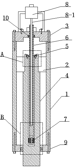
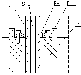
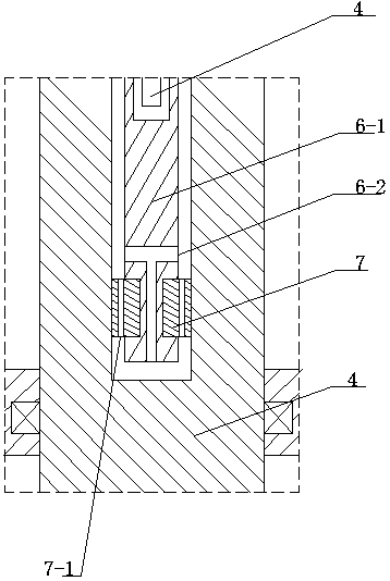
[0022] Such as Figures 1 to 3 As shown, an anti-rotation hydraulic cylinder piston rod displacement sensor installation structure includes a cylinder body 1, a cylinder bottom 3 is fixedly connected to the rear end of the cylinder body 1, an outer guide ring 9 is fixedly connected to the front end of the cylinder body 1; the piston rod 4 passes through The outer guide ring 9 and the rear end of the piston rod 4 are fixedly equipped with a piston 2 cooperating...


PUM


Abstract

The invention discloses an anti-rotating hydraulic cylinder piston rod displacement sensor mounting structure, and belongs to the technical field of hydraulic cylinders. A guide blind hole is formed in the axis position of the back end of a piston rod; the end part of the guide blind hole of the piston rod is fixedly connected with a middle guide ring; a guide rod is fixedly mounted in a cylinder bottom mounting through hole; the guide rod is a hollow rod, and penetrates through a polygonal hole in the center of the middle guide ring in a matching mode; a solid section is arranged at the inner end of the guide rod; an inner guide ring is fixedly mounted on the peripheral surface of the solid section; a displacement sensor is fixed on the outer side of the cylinder bottom; and a detecting rod in the displacement sensor is positioned in the guide rod. The main body of the hydraulic cylinder is not influenced by maintenance and replacement of the displacement sensor, so that the subsequent maintenance convenience and speediness are guaranteed; and the middle guide ring and the inner guide ring are used for matching with the guide rod, so that the guide blind hole of the piston rod needs no special machining process, the machining steps are greatly simplified, and the machining cost is reduced.

Description

technical field [0001] The invention relates to the technical field of hydraulic cylinders, in particular to a mounting structure for a piston rod displacement sensor of an anti-rotation hydraulic cylinder. Background technique [0002] The hydraulic cylinder is an actuator that converts hydraulic energy into linear motion mechanical energy. It has the characteristics of simple transmission structure and can transmit high-power work. It is widely used in construction machinery. At present, more and more hydraulic cylinders are equipped with built-in displacement sensors, which convert the physical quantity displacement of the hydraulic cylinder into values ​​that can be viewed at any time. [0003] Due to the complex working conditions of the hydraulic cylinder, the displacement sensor often needs to be repaired and replaced, and the existing installation structure of the displacement sensor is difficult to maintain, and generally the piston rod needs to be removed first. ...

Claims


Application Information

Patent Timeline
Patent Type & Authority Applications(China)
IPC IPC(8): F15B15/14F15B19/00
CPCF15B15/1428F15B15/1457F15B19/00
Inventor 王博文
Owner XUZHOU YONGJIA HYDRAULIC EQUIP
Why Eureka
Try Eureka