Hydraulic test table of electro-hydrostic actuator

An electro-hydrostatic actuation and hydraulic test technology, which is applied in the testing of fluid pressure actuation systems, servo meter circuits, fluid pressure actuation devices, etc., can solve the problems of low test efficiency, low test accuracy, and low degree of automation. Achieve the effect of saving labor cost and time cost, improving test efficiency and reliable test accuracy

Pending Publication Date: 2019-09-20
SHANGHAI UNIV
View PDF2 Cites 1 Cited by
  • Summary
  • Abstract
  • Description
  • Claims
  • Application Information

AI Technical Summary

Problems solved by technology

[0002] Electrostatic hydraulic actuator is a new type of power-by-wire system, which has an independent hydraulic source inside and integrates mechanical, electrical and hydraulic technologies. Compared with traditional hydraulic systems, it eliminates the comp

Method used


Image

  • Hydraulic test table of electro-hydrostic actuator
  • Hydraulic test table of electro-hydrostic actuator
  • Hydraulic test table of electro-hydrostic actuator

Examples


Embodiment 1

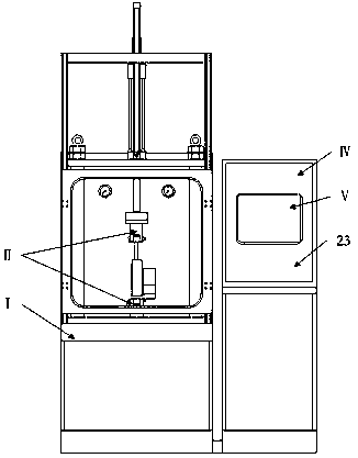
[0018] see Figure 1~Figure 4 , the hydraulic test bench of the electrohydrostatic actuator, including the test base (I), the test tool (II), the hydraulic system (III), the electric control system (IV) and the detection system (V), is characterized in that: The above-mentioned test fixture (II) is installed on the test base (I) and connected to the hydraulic system (III); the electric control system (IV) is connected to the hydraulic system (III) through cables; the components of the detection system (V) are installed in the hydraulic system system (Ⅲ), and connected to the electric control system (Ⅳ) through cables. The tested electrostatic hydraulic actuator is installed and disassembled on the test base (I) through the test tool (II), and the test is carried out through the hydraulic system (III). The electronic control system (IV) controls the hydraulic system (III) components and test The process is controlled, and the detection system (Ⅴ) collects the test data of the ...

Embodiment 2

[0019] Embodiment 2: This embodiment is basically the same as Embodiment 1, and the special features are as follows:

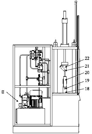
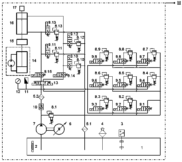
[0020] The test base (I) is a smooth and heavy square iron block, which is used to install the test tool (II) and withstand the loading force generated during the test; the test tool (II) includes a fixing fixture (18), a pin (19), the movable fixture (22) and the second pin (21), the first pin (19) connects the bottom of the electrohydrostatic actuator (20) to be tested with the fixed fixture (18), and the second pin (21) connects the The top of the electrostatic fluid actuator is connected with the movable fixture (22) to realize the installation and disassembly of the electrostatic fluid actuator under test; the hydraulic system (Ⅲ) includes an oil tank (1), two filters (5.1, 5.2 ), frequency conversion motor (6), gear pump (7), thirteen overflow valves (8.1~8.13), thirteen electromagnetic ball valves (9.1~9.13), check valve (10), electromagnetic reversing ...

Embodiment 3

[0022] As shown in the attached figure, the hydraulic test bench of the electrostatic hydraulic actuator includes a test base (I), a test tool (II), a hydraulic system (III), an electric control system (IV) and a detection system (V).


PUM


Abstract

The invention relates to a hydraulic test table of an electro-hydrostic actuator. The table comprises a test base, a test tool, a hydraulic system, an electric control system and a detection system. Through the test tool, mounting and dismounting of the tested electro-hydrostic actuator can be rapidly finished on the test base, the hydraulic system is used for testing the tested electro-hydrostic actuator, through the electric control system, the hydraulic system and the test process are controlled, through the detection system, test data in the test process can be collected and fed back to the electric control system to be analyzed and treated, the full-automatic test device is provided for the property test of the electro-hydrostic actuator, and the advantages of being high in test precision, high in test efficiency and high in practicability are achieved.

Description

technical field [0001] The invention relates to the field of hydraulic testing, in particular to a hydraulic test bench for an electrostatic fluid actuator. Background technique [0002] Electrostatic hydraulic actuator is a new type of power-by-wire system, which has an independent hydraulic source inside and integrates mechanical, electrical and hydraulic technologies. Compared with traditional hydraulic systems, it eliminates the complicated pipelines and Mechanical structure, high integration, more complex testing. At present, most of the test benches for electrostatic fluid actuators are controlled and tested manually, which has low test accuracy, low degree of automation, and low test efficiency. The invention designs a novel hydraulic test bench for the electrostatic fluid actuator, which can carry out fully automatic testing of the electrostatic fluid actuator. Contents of the invention [0003] The purpose of the patent of the present invention is to provide a h...

Claims


Application Information

Patent Timeline
IPC IPC(8): F15B19/00
CPCF15B19/00F15B19/005F15B2211/855F15B2211/87
Inventor 邢科礼尹礼胜李思亮姜克壮
Owner SHANGHAI UNIV
Why Eureka
Try Eureka