Efficient forced lubrication system with circulating lubrication function for coal mining machine

A technology of circulating lubrication and lubrication system, applied in the direction of gear lubrication/cooling, mechanical equipment, belt/chain/gear, etc., can solve the problems of lack of oil, low lubrication efficiency, inability to directly lubricate low-speed end bearings, etc., to achieve low production costs , High space utilization, the effect of simplifying the layout of oil passages

Pending Publication Date: 2019-09-20
SHANGHAI BRANCH TIANDI SCI&TECH CO LTD +1
View PDF0 Cites 1 Cited by
  • Summary
  • Abstract
  • Description
  • Claims
  • Application Information

AI Technical Summary

Problems solved by technology

[0002] At present, most of the rocker arms of coal shearers are equipped with forced lubrication systems. One typical structure is to install a lubricating pump at the high-speed end of the rocker arm, and pump the lubricating oil to the low-speed end through the lubricating pump. On the working surface, the bearing at the high-speed end of the lower rocker arm is short of oil; in addition, this structure generally only has one lubricating oil passage hole, which only leads to the end of the eight-axis assembly of the rocker arm, so it can only be The lubricating oil is introduced to the vicinity of the eight-axis assembly, and still cannot directly lubricate the low-speed end bearings, so the lubrication efficiency is low

Method used


Image

  • Efficient forced lubrication system with circulating lubrication function for coal mining machine
  • Efficient forced lubrication system with circulating lubrication function for coal mining machine
  • Efficient forced lubrication system with circulating lubrication function for coal mining machine

Examples


Embodiment Construction

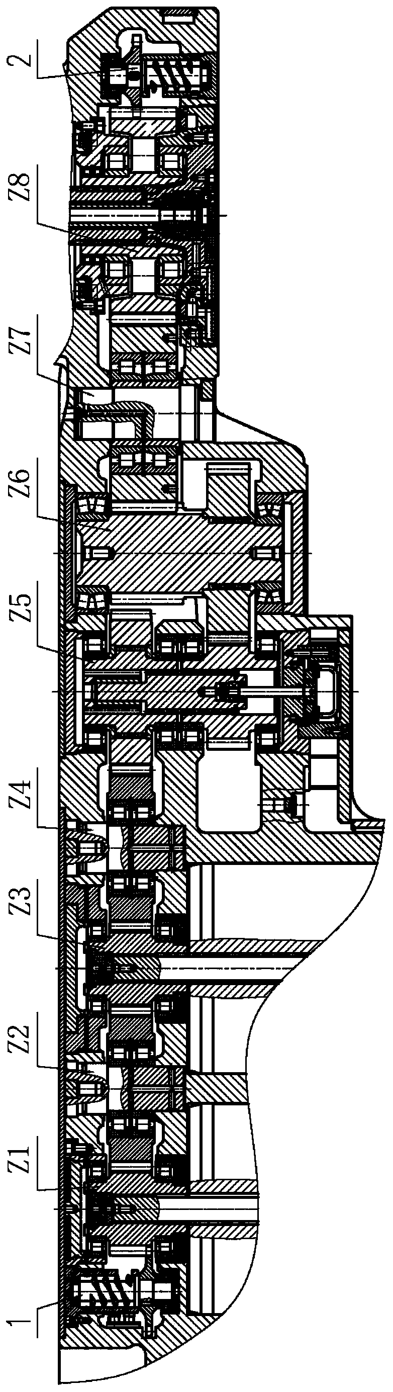
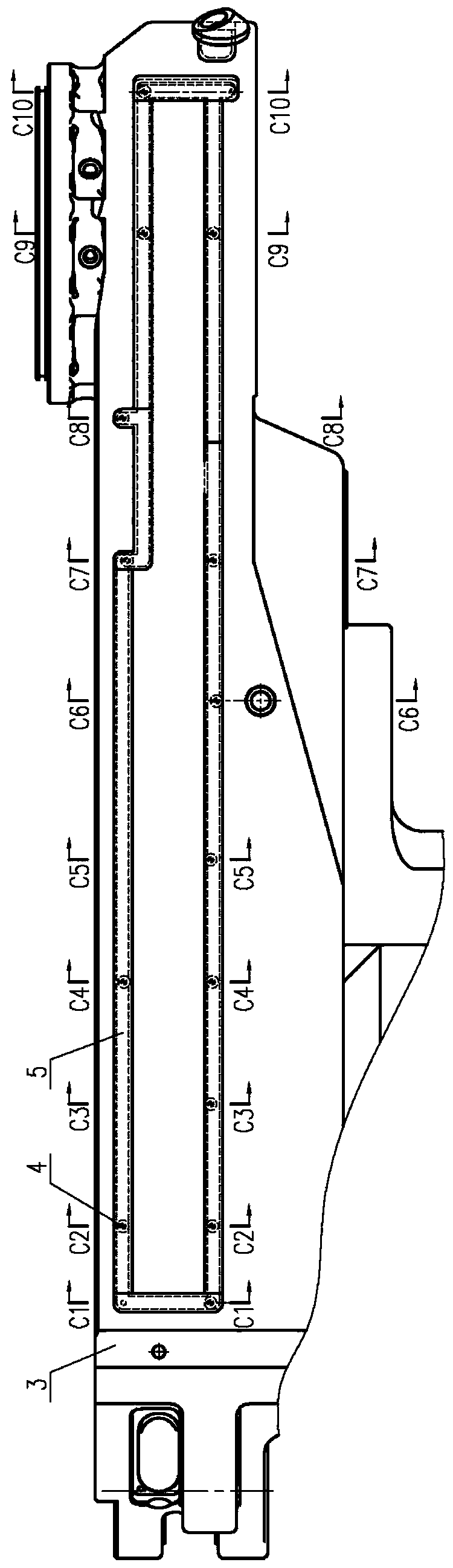
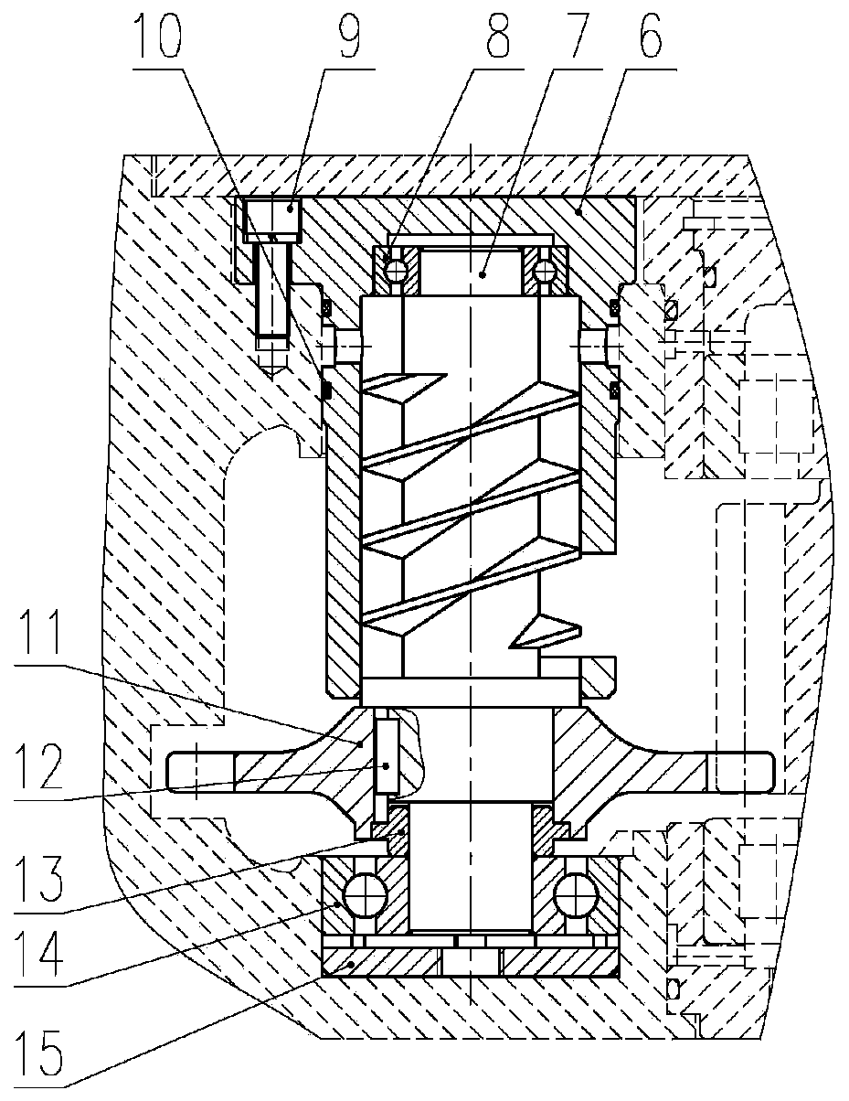
[0036] The invention discloses a high-efficiency forced lubrication system (lubrication system for short) of a coal shearer with a circulating lubrication function, such as Figure 1-15As shown, it includes high-speed lubricating pump 1, low-speed lubricating pump 2 and lubricating oil passages. The high-speed lubricating pump and low-speed lubricating pump are arranged in the transmission box of the rocker arm and form a row with each shaft of the rocker arm transmission system. Arranged in parallel and located on the outside of the first and last two shaft groups respectively, the first and last two shaft groups are respectively the shaft group with the highest speed and the shaft group with the lowest speed. The lubricating oil passage is arranged in the transmission box housing 3 of the rocker arm. The lubricating oil passage includes a main oil passage 16 and multiple sets of branch oil passages, and the main oil passage passes through the lubrication points of the branch...


PUM


Abstract

The invention relates to an efficient forced lubrication system with a circulating lubrication function for a coal mining machine. The efficient forced lubrication system comprises a high speed end lubrication pump, a low speed end lubrication pump and a lubrication oil passage, wherein the high speed end lubrication pump and the low speed end lubrication pump are arranged in a transmission case of a rocker arm; the lubrication oil passage is arranged in a transmission case housing of the rocker arm and comprises a main oil passage and multiple groups of branched oil passages; the main oil passage is communicated with the high speed end lubrication pump, the low speed end lubrication pump and lubricating points of all shaft assemblies of a diving system of the rocker arm, and is also communicated with oil discharge outlets of the high speed end lubrication pump and the low speed end lubrication pump. In the efficient forced lubrication system disclosed by the invention, one of the high speed end lubrication pump and the low speed end lubrication pump is always at low position at each time and can supply oil to the main oil channel, so that the main oil passage is always filled with oil; the oil is supplied to the high speed end lubrication pump, the low speed end lubrication pump and the lubricating points of all the shaft assemblies of the diving system of the rocker arm in real time through all the branched oil passages; even if the coal mining machine works on the work face with a large dip angle, all parts of the driving system of the rocker arm do not lack oil; the efficient forced lubrication system has high applicability.

Description

technical field [0001] The invention relates to a high-efficiency forced lubrication system of a coal mining machine, which is mainly used on the rocker arm parts of the coal mining machine to realize the high-efficiency lubrication of the shaft group bearings of the rocker arm transmission system. equipment technology field. Background technique [0002] At present, most of the rocker arms of coal shearers are equipped with forced lubrication systems. One typical structure is to install a lubricating pump at the high-speed end of the rocker arm, and pump the lubricating oil to the low-speed end through the lubricating pump. On the working surface, the bearing at the high-speed end of the lower rocker arm is short of oil; in addition, this structure generally only has one lubricating oil passage hole, which only leads to the end of the eight-axis assembly of the rocker arm, so it can only be The lubricating oil is introduced to the vicinity of the eight-axis assembly, and s...

Claims


Application Information

Patent Timeline
Patent Type & Authority Applications(China)
IPC IPC(8): F16H57/04
CPCF16H57/0424F16H57/0436F16H57/0441F16H57/0471
Inventor 李庆亮刘天宝翟雨生乐南更刘峰魏升郭岱王灿高振帮许寄桥金丹华
Owner SHANGHAI BRANCH TIANDI SCI&TECH CO LTD
Why Eureka
Try Eureka