Micro tower type solar heat collecting system

A tower-type solar energy and heat collection technology, which is applied in the field of solar energy collection, can solve the problems of high driving and tracking power requirements, high cost of motor equipment and control costs, and is not suitable for popularization and use. It achieves easy control process, small footprint, The effect of high-speed modular production

Pending Publication Date: 2019-09-20
西安神奇科技发展有限公司
View PDF0 Cites 0 Cited by
  • Summary
  • Abstract
  • Description
  • Claims
  • Application Information

AI Technical Summary

Problems solved by technology

[0002] At present, the solar heat collection system is an equipment structure with independent lens and dual motor tracking, and the power requirements for driving and tracking are high. Therefore, the cost of motor equipment and control costs are high. It is only suitable for large-scale heat collection systems and is not suitable for market promotion.

Method used


Image

  • Micro tower type solar heat collecting system
  • Micro tower type solar heat collecting system
  • Micro tower type solar heat collecting system

Examples


Embodiment 1

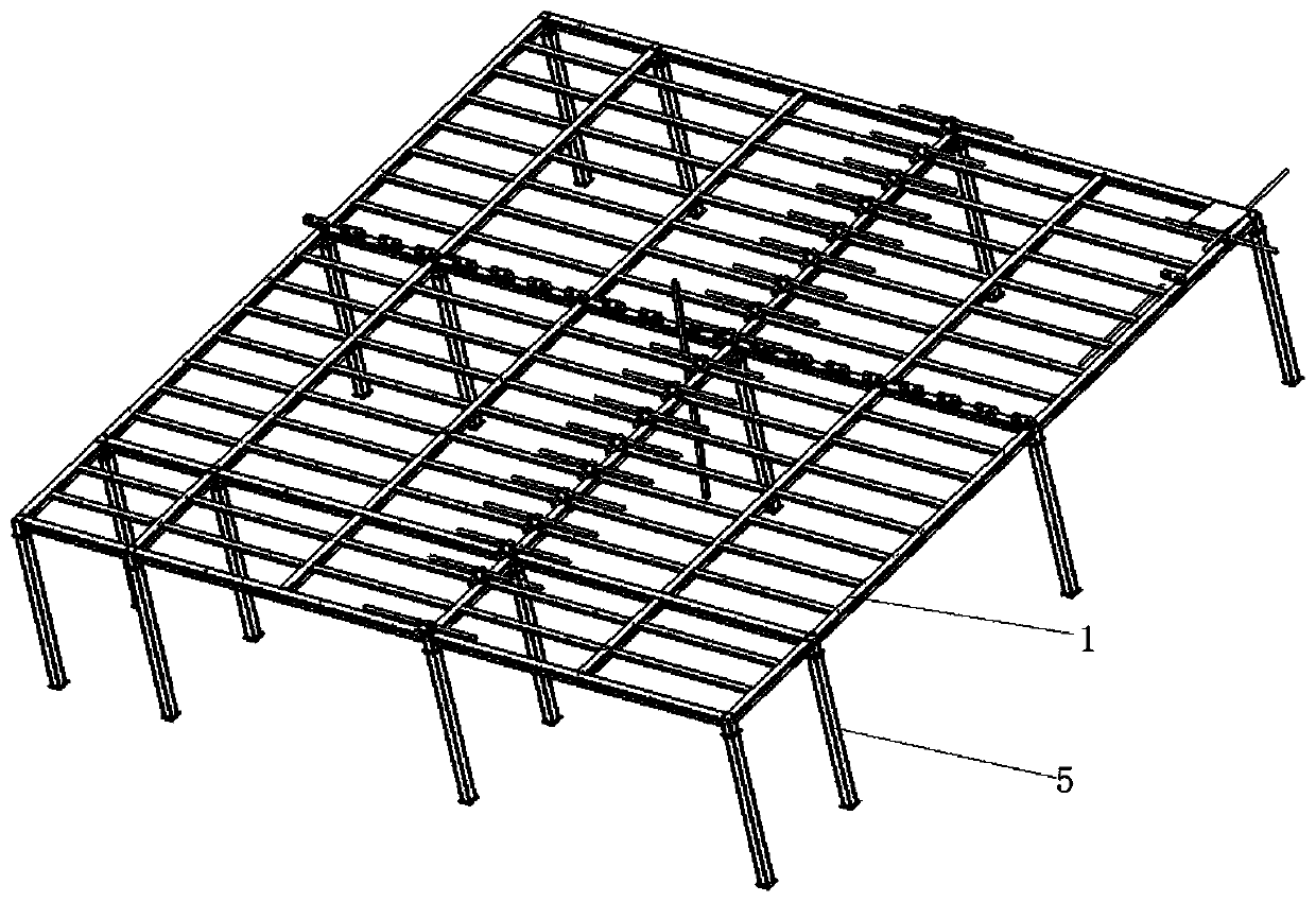
[0055] Such as figure 1 , figure 2 As shown, the micro-tower solar heat collection system includes a frame 1, a transmission device 2, a heat collection unit 3 and a circuit module 4; wherein:

[0056] The transmission device 2 is arranged on the frame 1;

[0057] There are multiple heat collecting units 3, all of which are set on the frame 1 through the transmission device 2;

[0058] The output end of the circuit module 4 is electrically connected to the transmission device 2 .

[0059] In the specific implementation process, the frame 1 is provided with a transmission device 2, and the working state of the transmission device 2 is controlled by the circuit module 4, thereby realizing the overall operation of a plurality of heat collection units 3, forming a multi-heat collection unit 3 The heat collection system reduces the driving power requirements, the whole control process is easy to realize, and the system can be adjusted according to the actual application occasio...

Embodiment 2

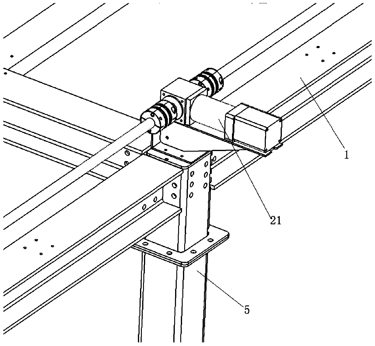
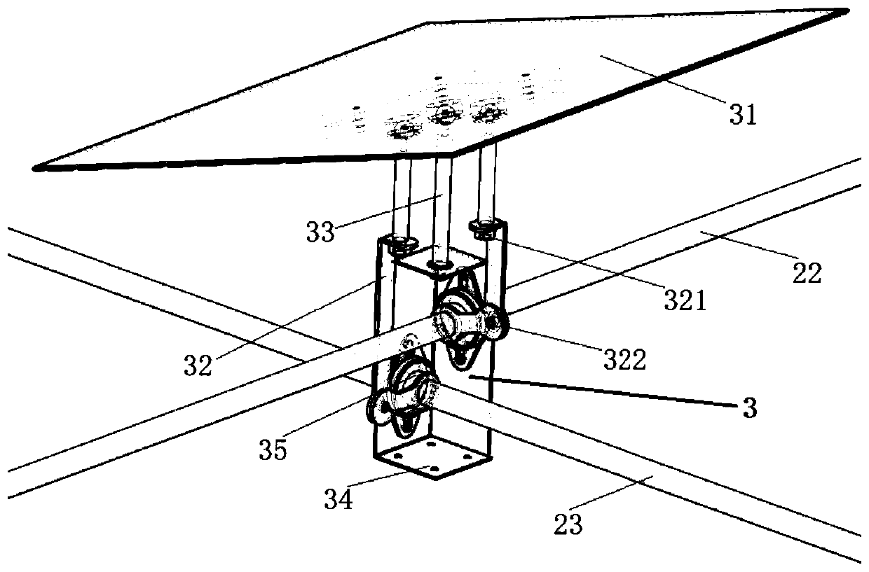
[0094] More specifically, on the basis of Embodiment 1, the transmission device also includes a transmission chain, and the transmission chain is arranged on the frame 1; the ends of the longitudinal transmission rod 22 and the transverse transmission rod 23 are all provided with The sprocket is arranged on the transmission chain through the sprocket; the driving motor 21 is connected with the transmission chain for controlling the rotation of the transmission chain.

[0095] In the specific implementation process, through the rotation of the transmission chain, through mechanical linkage and coaxial linkage, the use of motors is reduced, thereby driving the rotation of the longitudinal transmission rod 22 and the horizontal transmission rod 23, and then realizing the control of the heat collection direction of the heat collection unit , effectively reducing the number of driving motors 21, and greatly saving the cost of the system.

[0096] In the specific implementation proc...


PUM


Abstract

The invention provides a micro tower type solar heat collecting system which comprises a frame, a transmission device, a plurality of heat collecting units and a circuit module. The transmission device is arranged on the frame; the heat collecting units are arranged on the frame through the transmission device; and an output end of the circuit module is electrically connected to the transmission device. The invention provides the micro tower type solar heat collecting system. The heat collecting units work integrally to form a heat collecting system formed by the heat collecting units by controlling the working state of the transmission device through the circuit module. The power requirement on drive is reduced, and the whole control process is easily implemented. The system can be adjusted according to an actual application occasion is suitable for small application occasions and is beneficial to market application and use. Meanwhile, the system condenses light through a lens, so that high multiplying power, high precision and high speed modular production is achieved. The system is small in occupied area and high in condensing multiplying power and is quite suitable for heating, heat supply and heat for plants.

Description

technical field [0001] The invention relates to the technical field of solar energy collection, and more specifically, to a miniature tower solar heat collection system. Background technique [0002] At present, the solar heat collection system is an equipment structure with independent mirrors and dual motors for tracking. The power requirements for driving and tracking are high, so the cost of motor equipment and control is very high. It is only suitable for large-scale heat collection systems and is not suitable for market promotion. Contents of the invention [0003] In order to overcome the technical defects of the existing solar heat collection system, such as high power requirements for driving and tracking, high motor equipment cost and control cost, which are only applicable to large-scale heat collection systems and not suitable for market promotion, the present invention provides a Micro-tower solar heat collection system. [0004] In order to solve the problem...

Claims


Application Information

Patent Timeline
Patent Type & Authority Applications(China)
IPC IPC(8): F24S25/20F24S30/48F24S23/77
CPCF24S23/77F24S25/20F24S30/48Y02E10/47Y02P80/20
Inventor 芦维斌徐坚
Owner 西安神奇科技发展有限公司
Why Eureka
Try Eureka