Simulation device of condensate gas constant volume depletion in dense porous medium and experiment method

A technology of porous medium and simulation device, which is applied in the field of condensate gas reservoir development experiment, can solve the problems of small oil drainage area of ​​core section, small scale of condensate gas reservoir, differences in parameters, etc., and achieves reliable principle, great promotion value, Simple to use effects

Inactive Publication Date: 2019-09-20
CHINA PETROLEUM & CHEM CORP +1
View PDF5 Cites 7 Cited by
  • Summary
  • Abstract
  • Description
  • Claims
  • Application Information

AI Technical Summary

Problems solved by technology

CN1971273A discloses a test method for constant volume depletion of condensate gas reservoir fluid: starting from the dew point pressure, the constant fluid volume is depressurized step by step, the fluid is discharged, the oil and gas production are measured, and the components of the oil and gas are analyzed respectively. The recovery rate of natural gas and condensate oil and the amount of residual formation liquid in the depleted production process are obtained, but this method cannot determine the influence of porous media on the phase change of oil and gas, and only considers the macroscopic phase properties of the fluid, but in the actual condensate gas In the process of reservoir development, the influence of porous media on the fluid phase state cannot be ignored. It can even be said that some phase state parameters obtained through PVT experiments are different from those in actual porous media, which will inevitably affect the condensate. impact on the development of gas reservoirs
[0003] At present, the methods for simulating constant volume depletion of condensate gas in porous media mainly use long core depletion experiments (Sui Shuling. Experimental Research on Condensate Gas Depletion in Porous Media with Low Permeability, 2010, 32(3):97-100) or full-diameter depletion experiments. (Guo Ping. Dynamic Experimental Research on Depletion of Fracture-Cavity Condensate Gas Reservoirs, 2013, 35(2): 67-70), through these two depletion experiments to simulate the depletion development process of condensate gas r

Method used


Image

  • Simulation device of condensate gas constant volume depletion in dense porous medium and experiment method
  • Simulation device of condensate gas constant volume depletion in dense porous medium and experiment method
  • Simulation device of condensate gas constant volume depletion in dense porous medium and experiment method

Examples


Embodiment 1

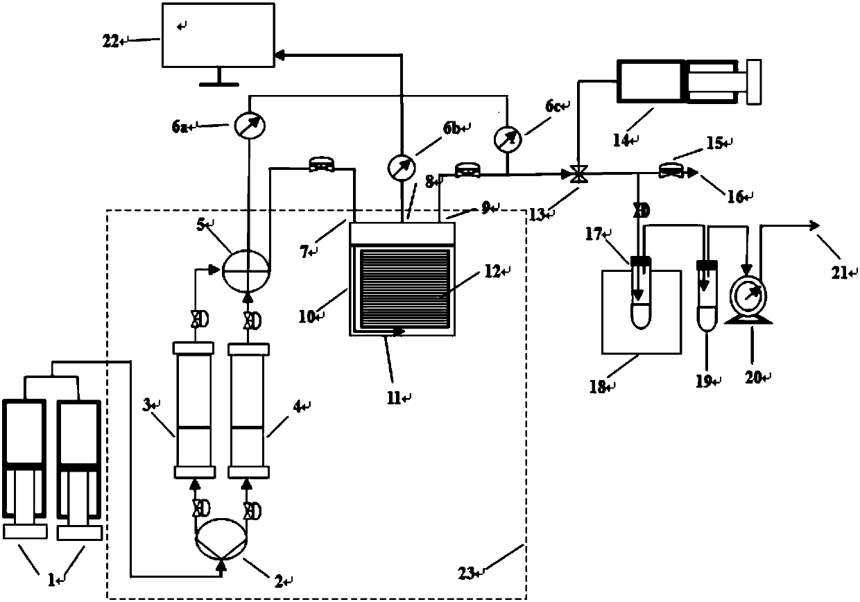
[0165] figure 1 A schematic structural diagram of a simulation device for constant volume depletion of condensate gas in dense porous media according to an exemplary embodiment of the present invention is shown.

[0166] Such as figure 1 As shown, a simulating device for constant volume depletion of condensate gas in dense porous media in this embodiment includes: a pressure supply module, a constant volume condensate gas reservoir module and an oil-gas separation module connected in sequence, wherein,

[0167] The constant volume condensate gas reservoir module includes a constant volume full diameter kettle 10, a first connecting pipeline 11 and a second connecting pipeline, the rock core 12 to be tested is arranged in the constant volume full diameter kettle 10, and the upper end cover of the constant volume full diameter kettle 10 An inlet hole 7, an outlet hole 9 and a pressure monitoring hole 8 are provided, and a first connecting pipeline 11 is used to connect the inle...

Embodiment 2

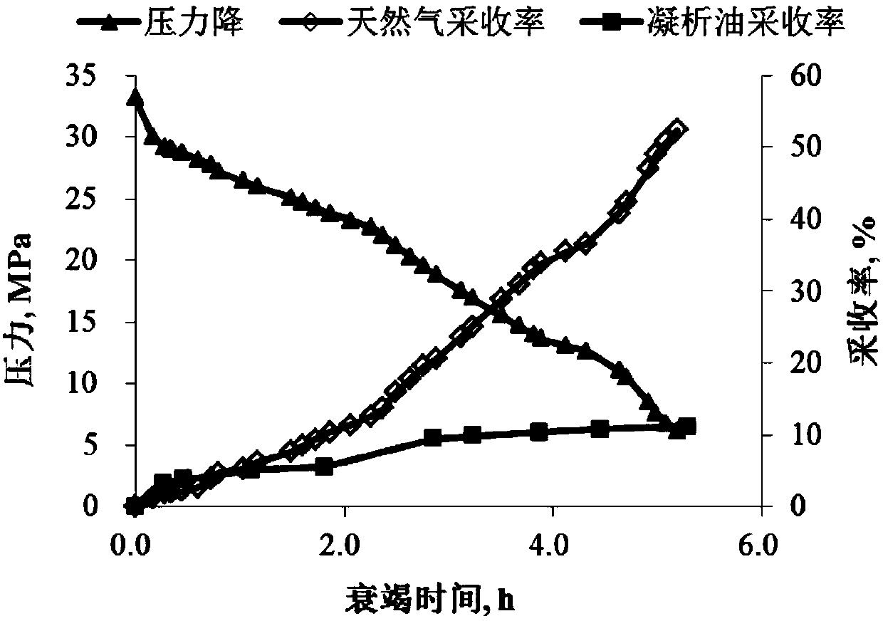
[0190] Example 2 is to carry out simulation development of condensate gas constant volume depletion in tight porous media for a condensate gas reservoir in China. The original formation pressure of the target layer is 31.4MPa, corresponding to the well depth temperature of 110.4°C, and there are fractures of different sizes around the gas well. According to the conventional PVT fluid phase state test report, it can be known that the dew point pressure of condensate gas under formation temperature and pressure is 26.23MPa. Based on the above data, a simulation test was carried out with the simulation device of Example 1.

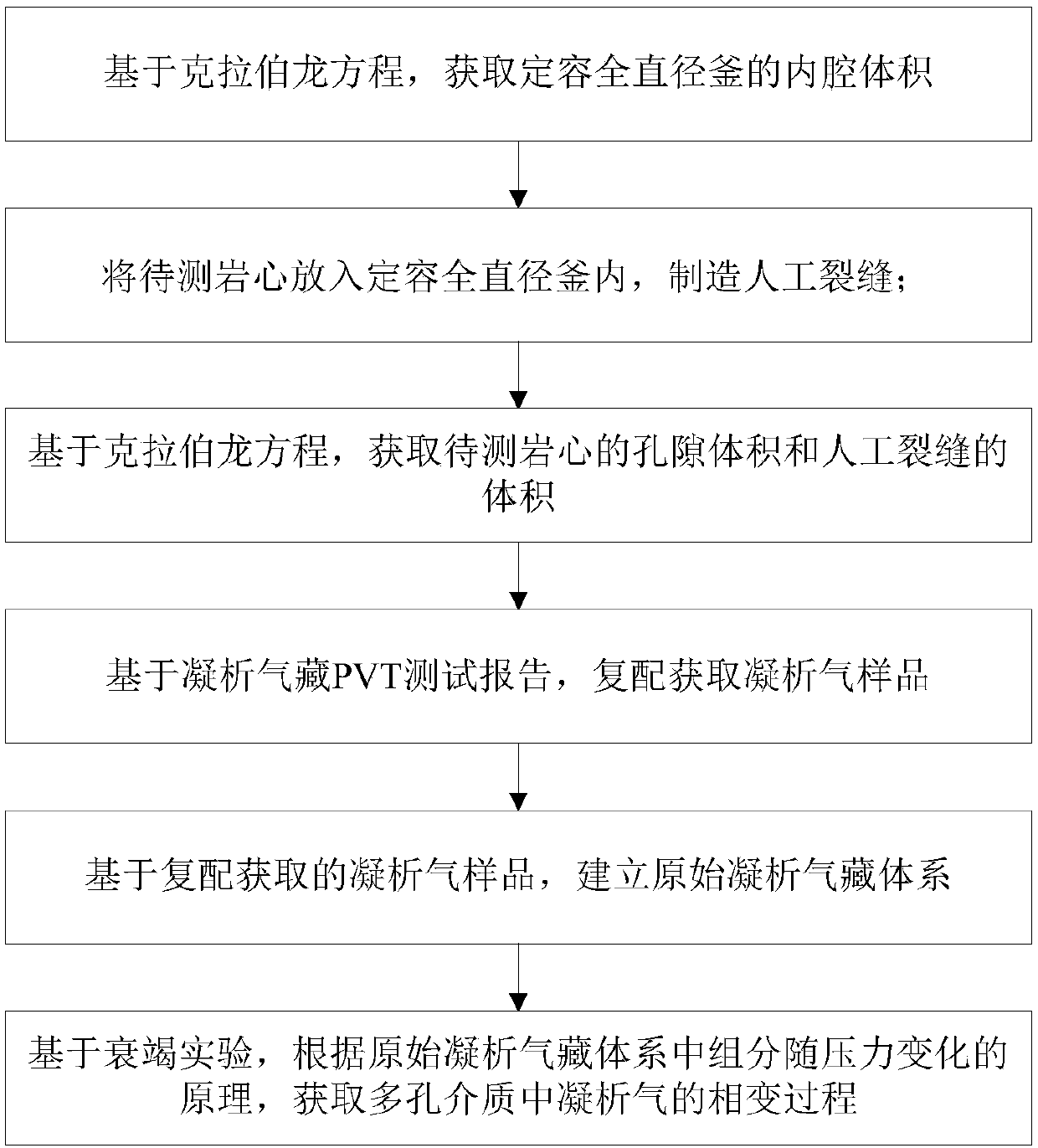
[0191] figure 2 A flow chart showing the steps of an experimental method for constant volume depletion of condensate gas in dense porous media according to an exemplary embodiment of the present invention.

[0192] Such as figure 2 As shown, the experimental method of constant volume depletion of condensate gas in a dense porous medium of the present embo...


PUM

PropertyMeasurementUnit
Diameteraaaaaaaaaa

Abstract

The invention discloses a simulation device of condensate gas constant volume depletion in a dense porous medium and an experiment method. The device comprises a constant volume condensate gas reservoir module, a pressure supply module and an oil and gas separation module, wherein in the constant volume condensate gas reservoir module, a core to be tested is placed in a constant volume full diameter kettle, an end cap is provided with an inlet hole, an outlet hole and a pressure monitoring hole, and a first connecting pipe line is connected to the inlet hole and a center of a circle of a bottom surface of the core to be tested; the pressure supply module includes a constant pressure constant speed displacement pump which is connected to one ends of a condensate gas intermediate container and a high pressure separator gas intermediate container, and the other ends of the condensate gas intermediate container and the high pressure separator gas intermediate container are connected to the inlet hole through the first connecting pipe line; and the oil and gas separation module includes a back pressure pump, a back pressure valve, an oil and gas separator and a gas meter which are connected successively, and an inlet end of the back pressure valve is connected to the outlet hole through a second connecting pipe line. The device and the method have advantages that changes of an oil and gas phase in a depletion process of a condensate gas reservoir in fractured tight reservoir can be simulated, and an oil and gas state under a condensate gas reservoir condition can be maximumly restored.

Description

technical field [0001] The invention relates to the technical field of condensate gas reservoir development experiments, and more specifically, to a simulation device and an experimental method for constant-volume depletion of condensate gas in dense porous media. Background technique [0002] Condensate gas reservoirs are the most "delicate" gas reservoirs among all types of oil and gas reservoirs. Once some mistakes occur in the development process, the impact on condensate gas reservoirs is irreversible. At present, theoretical methods and experimental techniques for the study of the phase state of condensate oil and gas systems have been gradually formed and gradually improved. Conventional phase state experiments are mainly carried out through high-temperature and high-pressure PVT kettles for single flash experiments, constant mass expansion experiments, and condensate inversion experiments. Quantitative experiments and constant volume depletion experiments are used to...

Claims


Application Information

Patent Timeline
IPC IPC(8): G01N33/24
CPCG01N33/24
Inventor 胡伟伦增珉吕成远王锐杨阳王欣
Owner CHINA PETROLEUM & CHEM CORP
Why Eureka
Try Eureka