
Optical lens, camera module and electronic device

A technology of optical lens and camera module, which is applied in the field of photography, can solve the problem of not being able to further meet higher-standard imaging requirements, and achieve uniform sensitivity distribution, standard refractive power distribution, and good correction effect

Active Publication Date: 2019-09-20
GUANGDONG OPPO MOBILE TELECOMM CORP LTD
View PDF3 Cites 1 Cited by
  • Summary
  • Abstract
  • Description
  • Claims
  • Application Information

AI Technical Summary

Problems solved by technology

[0002] Traditional light and thin optical imaging lenses mostly use four-element and five-element lens structures, but the four-element and five-element lens structures have limitations in terms of refractive power distribution, aberration astigmatism correction, and sensitivity distribution. Further meet higher specification imaging requirements

Method used


Image

  • Optical lens, camera module and electronic device
  • Optical lens, camera module and electronic device
  • Optical lens, camera module and electronic device

Examples


no. 1 approach

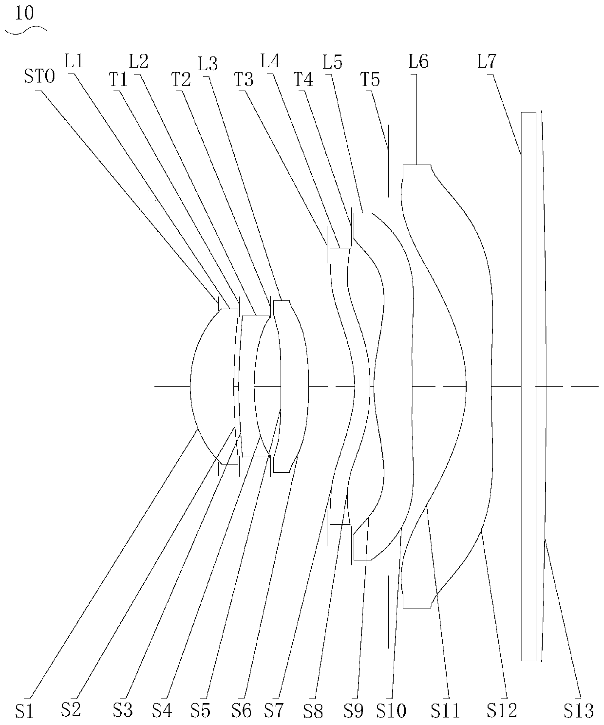
[0038] Please also refer to Figure 1 to Figure 5 The effective focal length of the optical lens 10 is EFL=4.41mm, the aperture number FNO=2.0 of the optical lens 10, half of the field of view angle of the optical lens 10 HFOV=41.6 degree, the optical total length TTL=5.19mm of the optical lens 10. The optical lens 10 satisfies the conditional formula: F2 / F1=-2.27; F3 / F1=2.63; F4 / F1=-1.52; R=-125mm; TTL / H=0.64. The optical lens 10 also meets the following table conditions:

[0039] Table 1

[0040]

[0041] Table 2

[0042]

[0043]

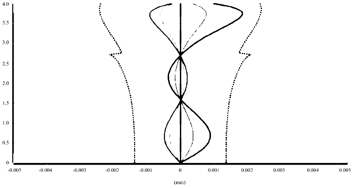
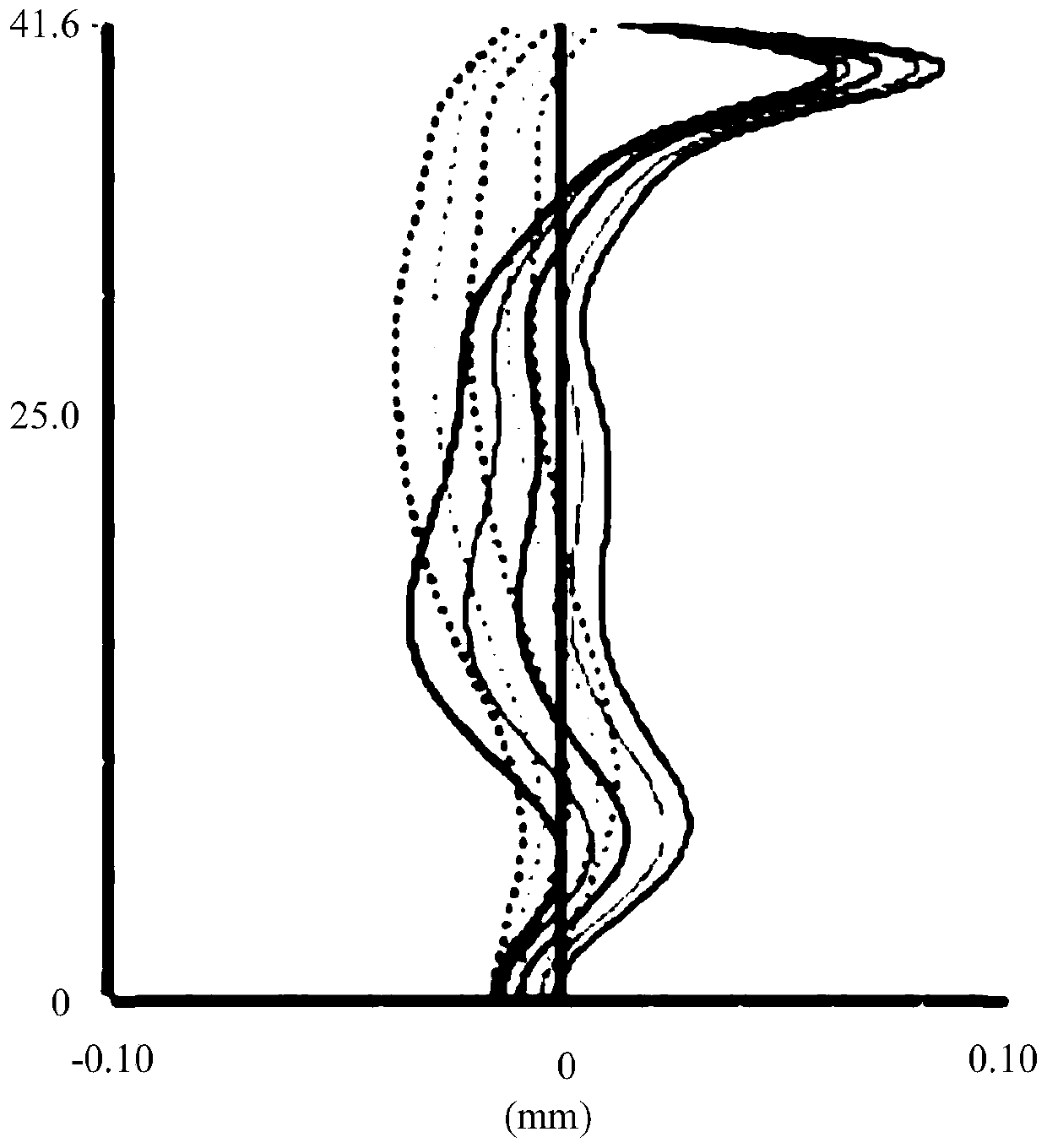
[0044] Depend on figure 2 It can be seen that the longitudinal chromatic aberration is controlled within ±0.002mm, and the aberration correction effect of the optical lens 10 is better. Depend on image 3 It can be seen that the full field of view of the field curvature is controlled within ±0.1mm, which optimizes the field curvature and improves the imaging quality. Depend on Figure 4 It can be seen that when the optical distor...

no. 2 approach

[0046] Please also refer to Figure 6 to Figure 10 , the effective focal length of optical lens 10 is EFL=4.45mm, the aperture number FNO=2.2 of optical lens 10, the half HFOV=41.7 degree of the field angle of optical lens 10, the optical total length TTL=5.2mm of optical lens 10. The optical lens 10 satisfies the conditional formula: F2 / F1=-2.25; F3 / F1=2.674; F4 / F1=-1.5; R=-137mm; TTL / H=0.651. The optical lens 10 also meets the following table conditions:

[0047] table 3

[0048]

[0049]

[0050] Table 4

[0051]

[0052] Depend on Figure 7 It can be seen that the longitudinal chromatic aberration is controlled within ±0.002mm, and the aberration correction effect of the optical lens 10 is better. Depend on Figure 8 It can be seen that the full field of view of the field curvature is controlled within ±0.1mm, which optimizes the field curvature and improves the imaging quality. Depend on Figure 9 It can be seen that when the optical distortion is less tha...


PUM

PropertyMeasurementUnit
Optical lengthaaaaaaaaaa

Abstract

The invention discloses an optical lens, a camera module, and an electronic device. The optical lens sequentially comprises a first lens with positive refractive power, a second lens with negative refractive power, a third lens with positive refractive power, a fourth with negative refractive power, a fifth lens with positive refractive power and a sixth with negative refractive power from an object side to an image side along an optical axis. An object side surface, close to the optical axis, of the first lens is a convex surface. An object side surface, close to the optical axis, of the second lens is a convex surface. An object side surface, close to the optical axis, of the third lens is a convex surface. An image side surface of the third lens is a concave surface. An object side surface, close to the optical axis, of the sixth lens is a concave surface. An image side surface, close to the optical axis, of the sixth lens is a concave surface. The image side surface of the sixth lens comprises at least one point of inflexion. The optical lens satisfies the following relations: -4<F2 / F1<0; 0<F3 / F1<4; -3<F4 / F1<0. The optical lens improves the correction effect of aberration and astigmatism through reasonably configuring the plurality of lenses, reduces the sensitivity of the optical lens, and has better image quality.

Description

technical field [0001] The present application relates to the technical field of photography, in particular to an optical lens, a camera module and an electronic device. Background technique [0002] Traditional light and thin optical imaging lenses mostly use four-element and five-element lens structures, but the four-element and five-element lens structures have limitations in terms of refractive power distribution, aberration and astigmatism correction, and sensitivity distribution. Further meet higher specification imaging requirements. Contents of the invention [0003] Embodiments of the present application provide an optical lens, a camera module and an electronic device. [0004] The optical lens according to the embodiment of the present application includes in sequence from the object side to the image side along the optical axis: a first lens with positive refractive power, a second lens with negative refractive power, a third lens with positive refractive powe...

Claims


Application Information

Patent Timeline
IPC IPC(8): G02B13/18
CPCG02B13/0045
Inventor 徐青
Owner GUANGDONG OPPO MOBILE TELECOMM CORP LTD
Features
  • Generate Ideas
  • Intellectual Property
  • Life Sciences
  • Materials
  • Tech Scout
  • Unparalleled Data Quality
  • Higher Quality Content
  • 60% Fewer Hallucinations
Learn More