
An automatic control system and method for a laser-guided car traveling route

A technology of automatic control system and traveling line, applied in control/adjustment system, vehicle position/route/height control, non-electric variable control and other directions, which can solve the problems affecting the positioning accuracy of the car, the cargo blocking the reflector, a large number of calculations, etc. problems, to avoid normal positioning, avoid deviation, and avoid storage effects

Active Publication Date: 2022-04-05
IBE ELECTRONICS CO LTD
View PDF0 Cites 0 Cited by
  • Summary
  • Abstract
  • Description
  • Claims
  • Application Information

AI Technical Summary

Problems solved by technology

[0006] (1) After the reflector is fixed, it usually cannot be moved, otherwise it will affect the positioning of the trolley. However, in actual use, due to the difference of the laser-guided trolley, the adjustment of the warehouse section, the accumulation of goods, etc., the reflector must be adjusted, but Each adjustment requires a lot of calculations and takes a lot of time, affecting the normal transportation of goods, and it is very likely that deviations will occur during multiple adjustments;
[0007] (2) Laser-guided trolleys are often used in warehouses and other places where there are many goods. Therefore, goods often block the reflection plate, which affects the positioning accuracy of the trolley. The common solution is to install more reflectors, but this does not It cannot fundamentally solve the problem, and too many reflectors will inevitably affect the storage of goods

Method used


Image

  • An automatic control system and method for a laser-guided car traveling route
  • An automatic control system and method for a laser-guided car traveling route
  • An automatic control system and method for a laser-guided car traveling route

Examples


Embodiment Construction

[0039] The following will clearly and completely describe the technical solutions in the embodiments of the present invention with reference to the accompanying drawings in the embodiments of the present invention. Obviously, the described embodiments are only some, not all, embodiments of the present invention. Based on the embodiments of the present invention, all other embodiments obtained by persons of ordinary skill in the art without making creative efforts belong to the protection scope of the present invention.

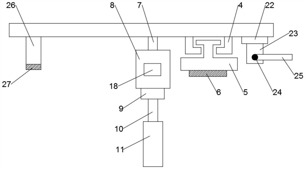
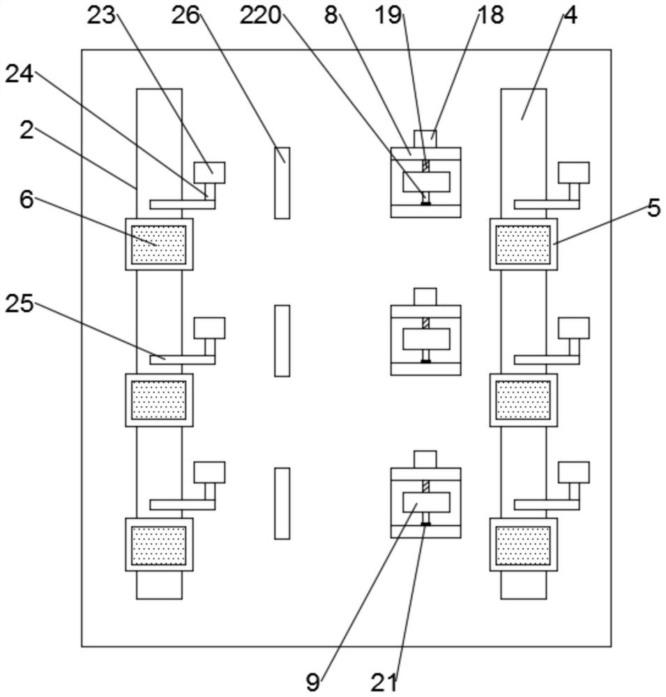
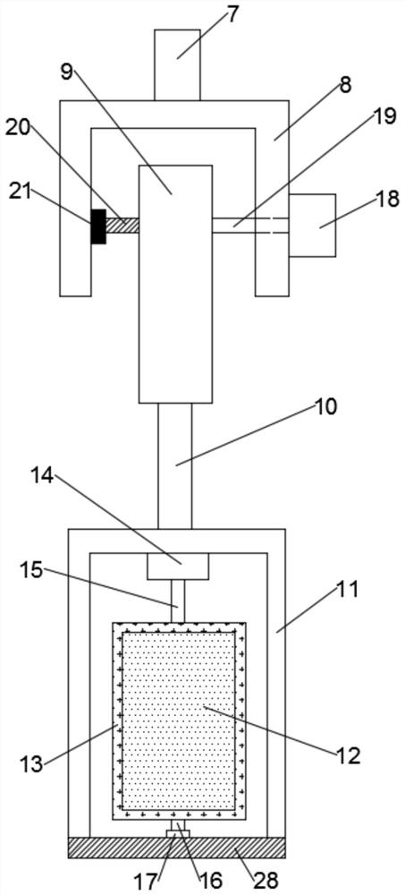
[0040] Such as Figure 1 to Figure 4 As shown, the present invention provides an automatic control system for the traveling route of a laser-guided trolley, including a car body 1 and a laser positioning mechanism 2, and a laser scanning device 3 is fixedly installed on the top of the car body 1, and the laser scanning device 3 is used for Laser light is emitted and received, and the laser positioning mechanism 2 is used to position the vehicle body 1 through ...


PUM


Abstract

The invention discloses an automatic control system and method for the traveling route of a laser-guided trolley, which includes a car body and a laser positioning mechanism. A laser scanning device is fixedly installed on the top of the car body. There are several electric mobile platforms, the bottom ends of the electric mobile platforms are fixedly equipped with horizontal reflectors, and the sides of the moving track are equipped with several support rods, and the bottom ends of the support rods are fixedly connected with mounting brackets. There are driving cylinders inside, and the output ends of the driving cylinders are connected to rectangular frames through lifting shafts, and vertical reflectors are arranged in the rectangular frames. This system can store various reflector arrangements during construction, so that it can be made The rapid adjustment of a large number of reflectors can avoid affecting the normal transportation of goods when the reflectors need to be adjusted due to special circumstances. At the same time, it can prevent the terrain or goods in the warehouse from blocking the reflectors and affecting the positioning of the trolley.

Description

technical field [0001] The invention relates to the field of intelligent transportation, in particular to an automatic control system and method for a laser-guided trolley traveling route. Background technique [0002] Automatic guided vehicle, also known as AGV, refers to automatic guidance equipment such as magnetic strips, rails or lasers, driving along a planned path, powered by batteries, and equipped with safety protection and various auxiliary mechanisms (such as transfer, Assembly mechanism) unmanned automated vehicles. Usually multiple AGVs and control computers (consoles), navigation equipment, charging equipment and peripheral auxiliary equipment form an AGV system. The main working principle is that under the monitoring and task scheduling of the control computer, the AGV can accurately follow the prescribed path. After arriving at the designated position of the task, a series of tasks are completed, and the control computer can decide whether to go to the charg...

Claims


Application Information

Patent Timeline
Patent Type & Authority Patents(China)
IPC IPC(8): G05D1/02
CPCG05D1/024G05D1/0259
Inventor 张亚南
Owner IBE ELECTRONICS CO LTD
Learn More