Remote-monitoring data transmission system

A data transmission system and remote monitoring technology, applied in the field of data transmission, can solve the problems of many transmission nodes, prone to failure, and high cost, and achieve the effect of reducing transmission nodes, solving costs, and low power consumption

Inactive Publication Date: 2019-09-20
TIANJIN UNIV OF SCI & TECH
View PDF10 Cites 0 Cited by
  • Summary
  • Abstract
  • Description
  • Claims
  • Application Information

AI Technical Summary

Problems solved by technology

[0004] The present invention provides a remote monitoring data transmission system to solve the problems of high cost, many transmission nodes, and easy failures raised in the above-mentioned background technology

Method used


Image

  • Remote-monitoring data transmission system

Examples


Embodiment Construction

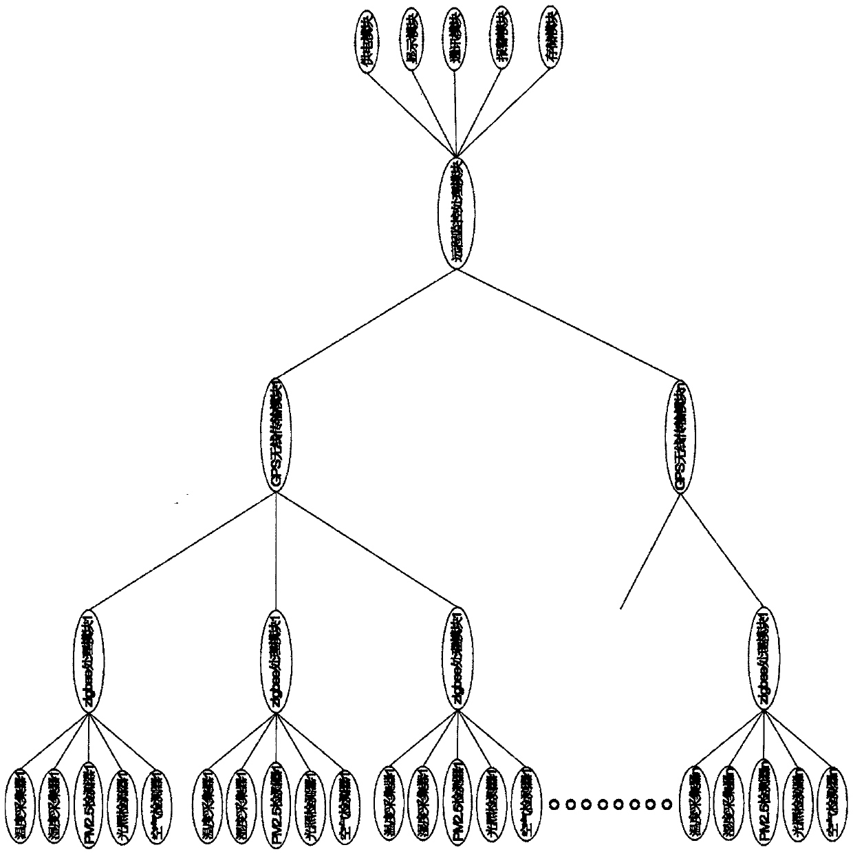
[0017] A remote monitoring data transmission system, comprising a temperature collector 1, a humidity collector 1, a PM2.5 detector 1, an illumination detector 1, and an air detector 1, the temperature collector 1, humidity collector 1, PM2. 5 Detector 1, light detector 1, and air detector 1 are all connected to Zigbee processing module 1;

[0018] Including temperature collector 2, humidity collector 2, PM2.5 detector 2, light detector 2, air detector 2, the temperature collector 2, humidity collector 2, PM2.5 detector 2, light detector 2. Air detector 1 is connected with Zigbee processing module 2;

[0019] Including temperature collector 3, humidity collector 3, PM2.5 detector 3, light detector 3, air detector 3, said temperature collector 3, humidity collector 3, PM2.5 detector 3, light detector 3. The air detectors 3 are all connected with a Zigbee processing module 3;

[0020] By analogy,...including temperature collector n, humidity collector n, PM2.5 detector n, ligh...


PUM


Abstract

The invention relates to a remote-monitoring data transmission system, and belongs to the technical field of data transmission. The system comprises a first temperature collector, a first humidity collector, a first PM2.5 detector, a first illumination detector and a first air detector all connected to a first Zigbee processing module to an nth temperature collector, an nth humidity collector, an nth PM2.5 detector, an nth illumination detector and an nth air detector all connected to an nth Zigbee processing module; and all the Zigbee processing modules are all connected with a first GPS wireless transmission module.

Description

technical field [0001] The invention belongs to the technical field of data transmission, in particular to a remote monitoring data transmission system. Background technique [0002] The remote monitoring system refers to the technology of controlling another computer (controlled host / server) by one computer (master remote / client) from a distance on the network. The remote here is not the literal meaning of long distance , generally refers to controlling the remote computer through the network, but most of the time what we call remote control often refers to the remote control in the local area network. When the operator uses the host computer to control the controlled computer, as if sitting in front of the screen of the controlled computer, the operator can start the application program of the controlled computer, use or steal the files and materials of the controlled computer, It is even possible to use the external printing device (printer) and communication device (mod...

Claims


Application Information

Patent Timeline
Patent Type & Authority Applications(China)
IPC IPC(8): G08C17/02G01D21/02
CPCG01D21/02G08C17/02
Inventor 姚伟张翠娟王昕
Owner TIANJIN UNIV OF SCI & TECH
Why Eureka
Try Eureka