
a chip substrate

A substrate and chip technology, applied to semiconductor/solid-state device parts, semiconductor devices, electrical components, etc., can solve problems such as loose soldering parts, poor contact of electronic components, and affect the accuracy of test data, so as to reduce the probability of movement , high friction, and the effect of reducing the chance of pin movement

Active Publication Date: 2020-12-11
日照菁英传媒科技有限公司
View PDF4 Cites 0 Cited by
  • Summary
  • Abstract
  • Description
  • Claims
  • Application Information

AI Technical Summary

Problems solved by technology

[0003] When simulating a car accident, it is necessary to place a variety of sensors in the vehicle. The electrode components on the internal substrate are welded by soldering. After a long period of time and high-density violent impact, the soldering parts are prone to loosening, causing electronic damage. Poor contact of components affects the accuracy of test data. In view of this, the present invention provides a chip substrate, which can reduce the looseness of soldering parts when soldering electronic components and improve the stability after installation.

Method used


Image

  • a chip substrate
  • a chip substrate
  • a chip substrate

Examples


Embodiment Construction

[0021] In order to make the technical means realized by the present invention, creative features, goals and effects easy to understand, the following will further elaborate the present invention in conjunction with specific embodiments. figure 2 view direction.

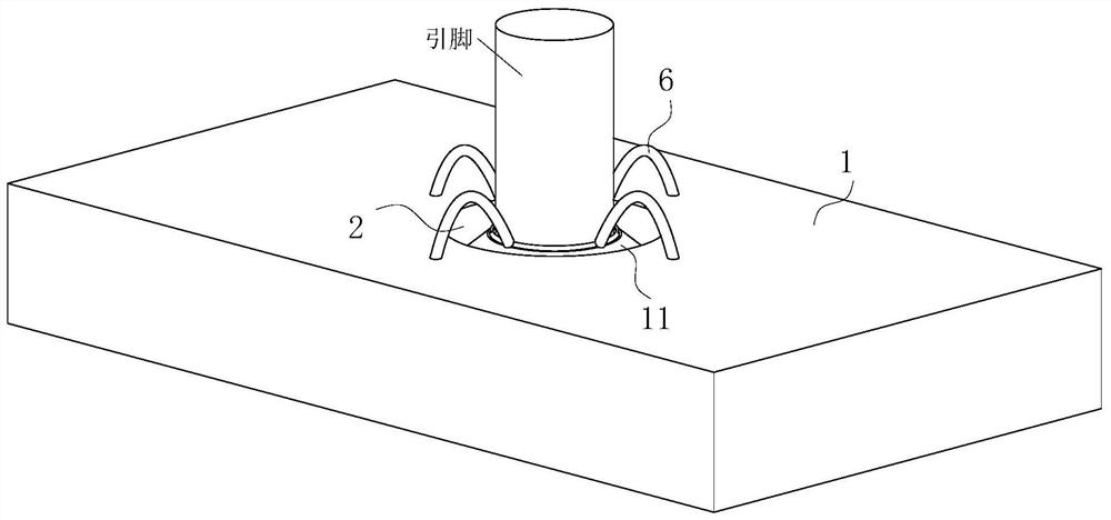
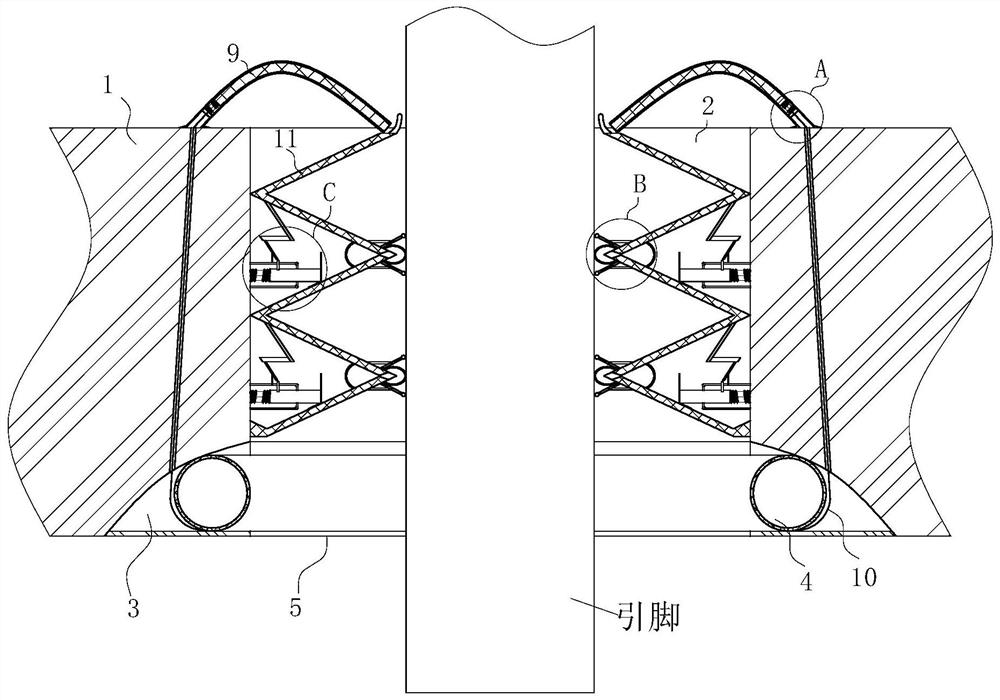
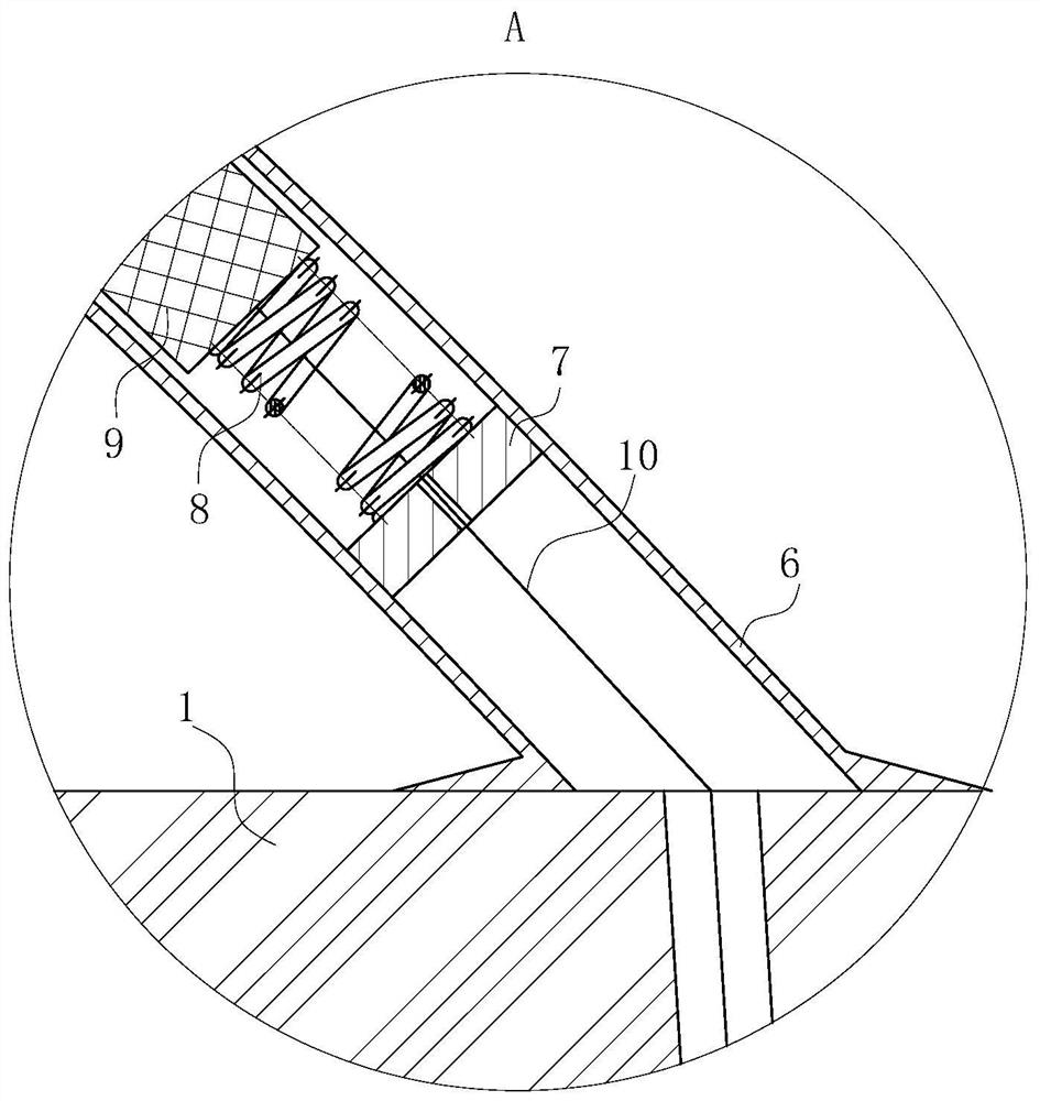
[0022] Such as Figure 1-5 As shown, a chip substrate according to the present invention includes a substrate body 1, a plurality of mounting holes 2 are opened on the surface of the substrate body 1, and an annular groove 3 is opened on the substrate body 1 at the bottom end of the mounting holes 2. , the annular groove 3 is provided with an annular ring 4, the bottom of the annular ring 4 is provided with an annular plate 5, the lower surface of the annular plate 5 is flush with the lower surface of the substrate body 1 and is firmly connected to each other, and the upper surface of the substrate body 1 An elbow 6 is fixedly connected, the inside of the elbow 6 is provided with a fixing plate 7, and the top of the...


PUM


Abstract

The present invention belongs to the technical field of semiconductor devices, in particular to a chip substrate comprising a substrate body. The surface of the substrate body are provided with a plurality of mounting holes, and the substrate body at the bottom end of the mounting holes is provided with an annular groove. An annular ring is arranged in the annular groove; an annular plate is arranged at the bottom of the annular ring; and the lower surface of the annular plate is flush and fixedly connected with the lower surface of the substrate body. The invention arranges the annular groove and a rubber rod so that when the annular ring is broken after a pin is mounted, the annular ring shrinks and a force applying spring pushes the rubber rod in an elbow to move; the rubber rod is extruded from the elbow and applies a downward thrust to the pin. At the same time, soldering tin is solidified after cooled and is located in the annular groove where the annular ring is broken and shrinks so that the sliding probability of the soldering tin is reduced. Simultaneously the soldering tin is solidified together with a stay cord; an upward thrust is applied to the stay cord by the force applying spring; thereby there is a tension effect on the soldering tin; and the moving probability of a welding part is further reduced.

Description

technical field [0001] The invention belongs to the technical field of semiconductor equipment, in particular to a chip substrate. Background technique [0002] The chip substrate is the packaging substrate, which is a term in printed circuit boards. The substrate can provide electrical connection, protection, support, heat dissipation, assembly and other functions for the chip to achieve multi-pin, reduce the volume of packaged products, and improve electrical performance and heat dissipation. , ultra-high density or multi-chip modularization purposes. [0003] When simulating a car accident, it is necessary to place a variety of sensors in the vehicle. The electrode components on the internal substrate are welded by soldering. After a long period of time and high-density violent impact, the soldering parts are prone to loosening, causing electronic damage. Poor contact of components affects the accuracy of test data. In view of this, the present invention provides a chip ...

Claims


Application Information

Patent Timeline
Patent Type & Authority Patents(China)
IPC IPC(8): H01L23/49
CPCH01L23/49
Inventor 吴彬王浩吴爱兵
Owner 日照菁英传媒科技有限公司
Learn More