
Self-feedback LED control method and system

A control method and self-feedback technology, applied in the field of self-feedback LED control methods and systems, can solve problems such as device loss, inability to cope with LED switch control, and inability to realize high-frequency periodic switching application control, so as to improve device control The effect of precision

Active Publication Date: 2019-09-20
NINGBO JIUZONG INTELLIGENT TECH
View PDF5 Cites 4 Cited by
  • Summary
  • Abstract
  • Description
  • Claims
  • Application Information

AI Technical Summary

Problems solved by technology

In the existing application technology of LED (Light Emitting Diode, light-emitting diode) control, for the control of LED, the existing control technology currently only exists LED switch control below 1KHZ, for high-frequency switch control, for example, the application number is 201810164212.1 , the name is a water-cooled high-power high-frequency switching power supply device, which realizes high-frequency switching, but this solution is used in large-scale power systems, and the devices involved are bulky and cannot be applied to LED control solutions. For the LED switch control above 1KHZ, especially the LED switch control of 1KHZ-20KHZ, there is no suitable method at present, and the existing low-frequency LED control method below 1KHZ cannot cope with the high-frequency LED switch control of 1KHZ-20KHZ , causing the current LED switch control in the frequency band of 1KHZ-20KHZ to be in a blank state
[0003] In the prior art, LED control is only a simple duty cycle control or input current regulation, and it is impossible to realize combined high-frequency periodic switching application control
[0004] In the prior art, after the LED lamps are used for a period of time, the luminous brightness will attenuate due to device loss, which will affect the control accuracy of the LED lamps.

Method used


Image

  • Self-feedback LED control method and system
  • Self-feedback LED control method and system
  • Self-feedback LED control method and system

Examples


Embodiment

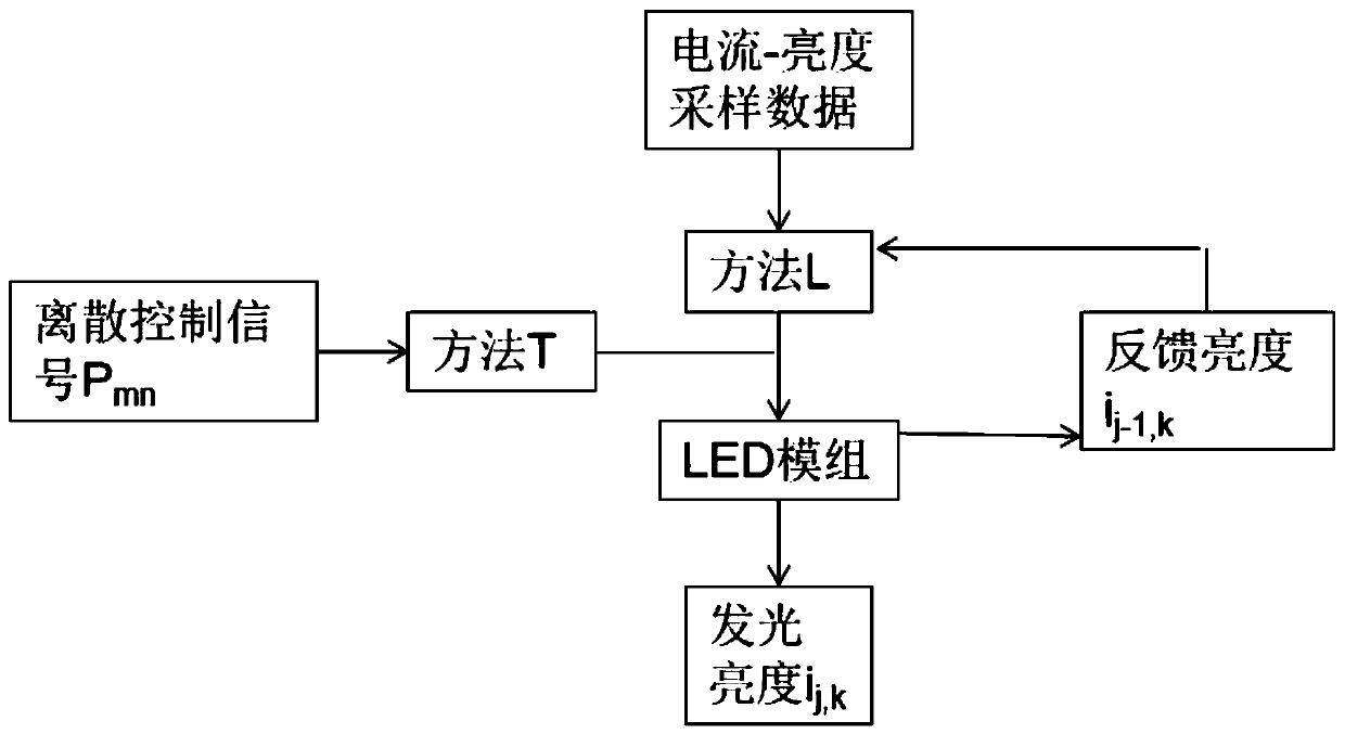
[0054] Such as figure 1 As shown, this embodiment provides a self-feedback LED control method, which can be used to control the lighting mode of a single or multiple LED modules, especially suitable for single or multiple LED modules at 1KHZ-20KHZ Under the high-frequency opening and closing control.

[0055] Specifically, the self-feedback LED control method includes:

[0056] S1: According to the light-emitting characteristics of the LED itself, set the control parameter P in the opening and closing control of the frequency f, taking m frequencies as a control cycle, and realizing the brightness control of n LEDs in a specified way in each control cycle m,n :

[0057] P m,n ={a 1,1 a 1,2 a 1,3 ...a 1,N , a 2,1 a 2,2 a 2,3 ...a 2,n , ................................ a m,1 a m,2 a m,3 ...a m,n};

[0058] S2: will control the parameter P m,n , Quantify the control relationship between the frequency f and the theoretical input current of the LED, and est...


PUM


Abstract

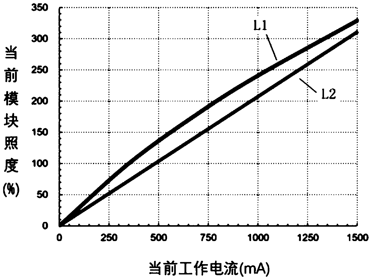
The invention provides a self-feedback LED control method and a system. According to the method, m frequencies are set as a control period in the on-off control of the frequency f, and control parameters Pm, n of n LEDs in the specified brightness control mode are realized in each control period; the control relationship between the control parameters Pm, n, the frequency f and the theoretical input current of the LED is quantized, and an algorithm model is established; the relationship between the input current C and the output brightness iL is linearized and the algorithm model is established; and the combination of self-feedback and quantization and linearization is performed. The LED control method is particularly suitable for high-frequency quantitative on-off control of single or multiple LED modules at the frequency of 1KHZ-20KHZ, and the actual brightness can be kept constant and the brightness varies linearly when the input current is adjusted. Besides, the brightness can be adjusted in case of brightness decay in the long-term use so that the brightness is constant in the control range and the control accuracy of the device can be enhanced.

Description

technical field [0001] The invention relates to the technical field of LED lighting, in particular to a self-feedback LED control method and system. Background technique [0002] LED lamps have low heat generation, low power consumption, and strong controllability, and are currently vigorously promoted as energy-saving light sources. In the existing application technology of LED (Light Emitting Diode, light-emitting diode) control, for the control of LED, the existing control technology currently only exists LED switch control below 1KHZ, for high-frequency switch control, for example, the application number is 201810164212.1 , the name is a water-cooled high-power high-frequency switching power supply device, which realizes high-frequency switching, but this solution is used in large-scale power systems, and the devices involved are bulky and cannot be applied to LED control solutions. For the LED switch control above 1KHZ, especially the LED switch control of 1KHZ-20KHZ, ...

Claims


Application Information

Patent Timeline
Patent Type & Authority Applications(China)
IPC IPC(8): H05B33/08H05B44/00
CPCH05B45/00
Inventor 赖勉力冯裕
Owner NINGBO JIUZONG INTELLIGENT TECH
Learn More