Machining equipment for large tapered roller pin hole and machining process thereof

A technology for tapered rollers and processing equipment, applied in metal processing equipment, drilling/drilling equipment, other manufacturing equipment/tools, etc., can solve the problem of pin hole contact with knife marks, large runout, and misalignment between pin hole and cone surface To achieve the effect of ensuring product accuracy and yield, reducing the possibility of pinching, and improving concentricity

Active Publication Date: 2019-09-24
WUXI YITONG PRECISION MACHINERY
View PDF5 Cites 2 Cited by
  • Summary
  • Abstract
  • Description
  • Claims
  • Application Information

AI Technical Summary

Problems solved by technology

[0004] The pin hole processing method in the existing technology is very easy to cause problems such as misalignment between the pin hole and the cone surface, large jump, and tool marks on the pin hole. The technical requirements for the processing personnel are high, and the product accuracy cannot be guaranteed, nor can it To ensure product yield, therefore, it is necessary to improve the pin hole processing technology and related equipment

Method used


Image

  • Machining equipment for large tapered roller pin hole and machining process thereof
  • Machining equipment for large tapered roller pin hole and machining process thereof
  • Machining equipment for large tapered roller pin hole and machining process thereof

Examples


Embodiment Construction

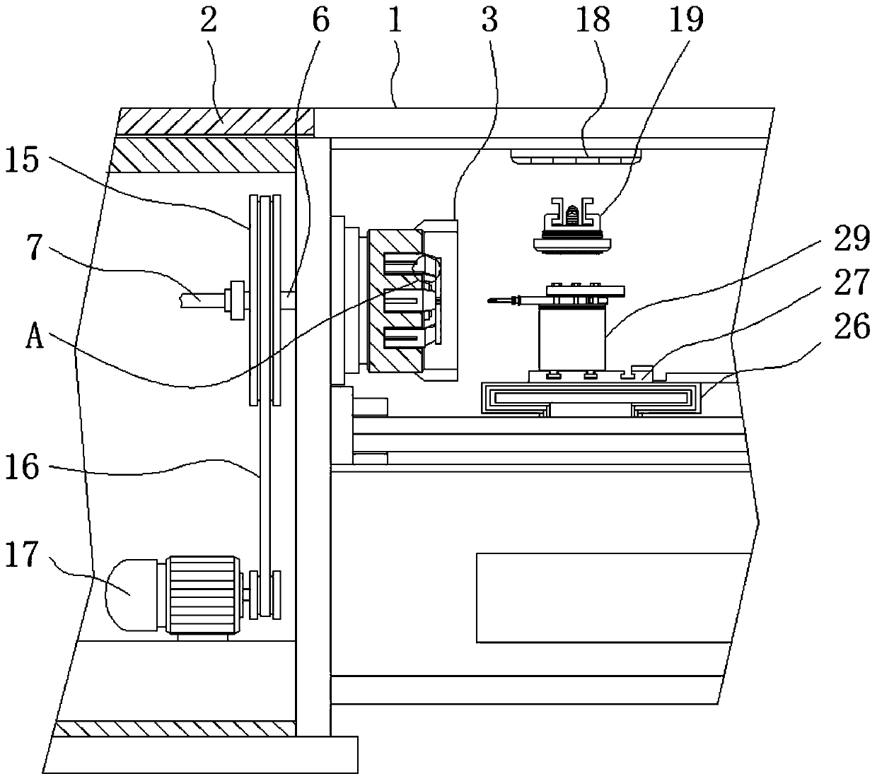
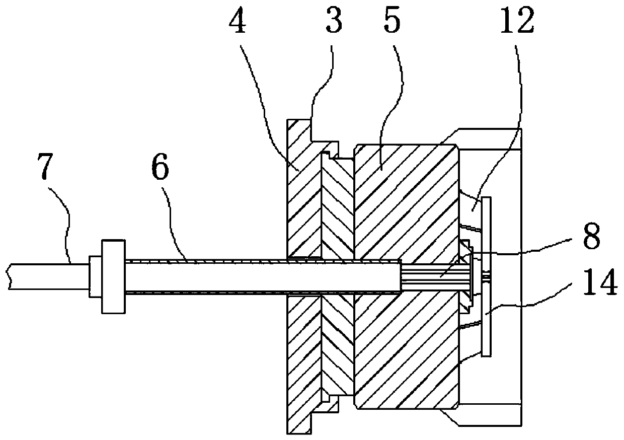
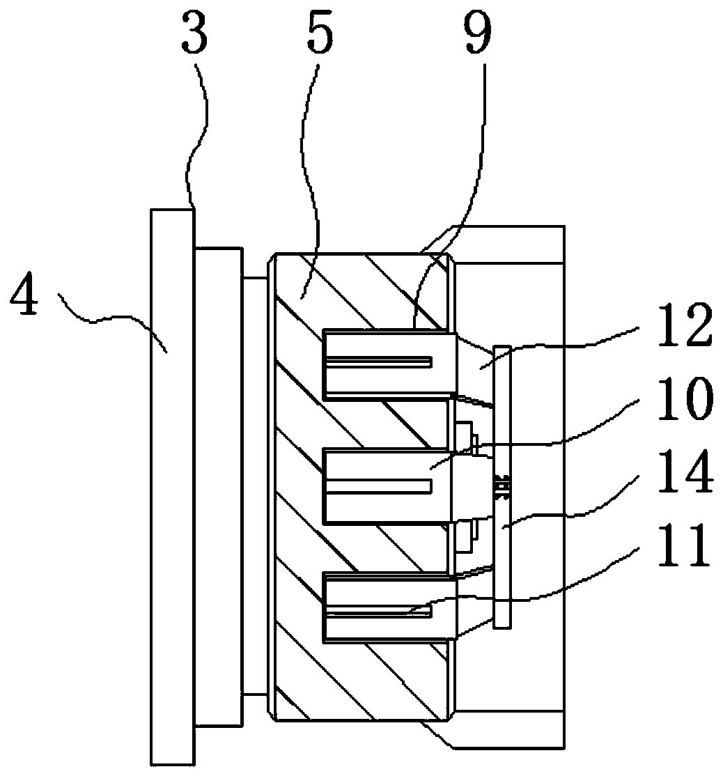
[0045] The following will clearly and completely describe the technical solutions in the embodiments of the present invention with reference to the accompanying drawings in the embodiments of the present invention. Obviously, the described embodiments are only some, not all, embodiments of the present invention.

[0046] In the description of the present invention, unless otherwise stated, the meaning of "plurality" is two or more; the terms "upper", "lower", "left", "right", "inner", "outer" , "front end", "rear end", "head", "tail", etc. indicate the orientation or positional relationship based on the orientation or positional relationship shown in the drawings, and are only for the convenience of describing the present invention and simplifying the description, rather than Nothing indicating or implying that a referenced device or element must have a particular orientation, be constructed, and operate in a particular orientation should therefore not be construed as limiting th...


PUM


Abstract

The invention discloses machining equipment for a large tapered roller pin hole and a machining process thereof and relates to the technical field of machining of large tapered roller pin holes. The machining equipment particularly comprises a machine tool, a clamping body, a chip cleaning mechanism and a distance adjusting rod set. A sliding door is installed outside the machine tool. The clamping body is arranged on one side in the machine tool. A hollow rotary shaft penetrates through one side of the clamping body. The outer side of an end of the hollow rotary shaft is sleeved by a belt wheel. A transmission motor is installed at the other end of a transmission belt. The chip cleaning mechanism is transversely arranged on the upper portion in the machine tool. The distance adjusting rod set is clamped between a cutter clamping seat and a cutter clamping plate. According to the machining equipment for the large tapered roller pin hole and the machining process thereof, an original common drill bit is changed to a U drill, thus a workpiece can be punched once, a boring cutter for finish turning of an inner hole is changed to a shakeproof long rod boring cutter, and boring of the inner hole is completed once. Through the machining process, a gear mark of the inner hole of the workpiece is avoided, turning-round secondary drilling and boring are not needed, and concentric accuracy of the inner hole and a conical face is improved.

Description

technical field [0001] The invention relates to the technical field of large tapered roller pin hole processing, in particular to a large tapered roller pin hole processing equipment and processing technology. Background technique [0002] The pin hole is also used as a positioning pin hole. It is a hole designed to insert a positioning pin for accurate positioning of parts or workpieces. Accuracy, resulting in positioning deviation, so the pin hole in the production process, the precision requirements are high, need to pay special attention to the formulation of the production process. [0003] The existing large tapered roller pin hole processing technology is to clamp one end of the large roller on the ordinary car, punch half of the hole, then turn around and clamp it again, and then punch through. In this way, the holes punched twice will not be concentric, and there will be gaps. There will also be eccentricity in the finish turning of the conical surface and the hole...

Claims


Application Information

Patent Timeline
Patent Type & Authority Applications(China)
IPC IPC(8): B23P23/02B23P15/00B23B41/00
CPCB23B41/00B23P15/00B23P23/02
Inventor 易阳
Owner WUXI YITONG PRECISION MACHINERY
Why Eureka
Try Eureka