Collosol feeding mechanism capable of removing moisture for injection molding machine

An injection molding machine and plastic injection technology, which is applied in the field of plastic injection molding, can solve the problems of wasting electric energy, high rejection rate, and inability to operate alone, and achieve the effects of reducing electric energy consumption, improving the efficiency of sol material storage, and improving the effect of exhaust and dehumidification.

Pending Publication Date: 2019-09-24
李伟
View PDF0 Cites 0 Cited by
  • Summary
  • Abstract
  • Description
  • Claims
  • Application Information

AI Technical Summary

Problems solved by technology

[0003] There are many types of plastic raw materials used in existing injection molding machines, but for secondary recycled plastics, water needs to be removed before they can be used for injection molding. Most of the current methods on the market are to dry the secondary recycled plastics first or use a single-screw belt row. The air tank removes moisture, and then processes injection molding or extrusion molding, but it has the disadvantages of wasting electric energy and high scrap rate
At the same time, the existing injection molding machine uses a hydraulic motor to drive the screw to rotate, and uses the oil pump as the main power source of the injection molding machine, which cannot be operated independently

Method used


Image

  • Collosol feeding mechanism capable of removing moisture for injection molding machine
  • Collosol feeding mechanism capable of removing moisture for injection molding machine

Examples


Embodiment Construction

[0013] Embodiments of the present invention will be further described below with reference to the accompanying drawings:

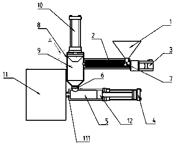
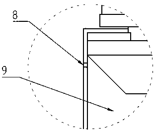
[0014] Such as Figure 1-Figure 2 As shown, the present embodiment provides an exhaust sol feeding mechanism for an injection molding machine, including a feeding port 1, an injection molding power mechanism 4, an injection plastic cylinder 5, and a forming mold 11. The forming mold 11 is provided with an injection port 111, and Including a check valve 6 and an accumulator cylinder 9, the injection port 111 of the forming mold 11 is connected to the plastic injection cylinder 5, and the head of the injection molding power mechanism 4 is equipped with an injection molding screw 12, and the injection molding screw 12 is located on the injection molding cylinder. The inside of the cylinder 5 is linearly moved by the injection molding power mechanism 4. The outlet of the one-way valve 6 is installed above the injection plastic cylinder 5. The inlet of the one-...


PUM


Abstract

The invention relates to the technical field of plastic injection molding, in particular to injection molding equipment for secondary recovery of plastic. A feeding port, an injection molding power mechanism, an injection molding material barrel and a forming mold are involved, wherein an injection molding opening is formed in the forming mold, and a one-way valve and a material storing cylinder are involved, wherein the injection molding opening of the forming mold is connected with the injection molding material barrel, an injection molding screw rod is installed at the head part of the injection molding power mechanism, the injection molding screw rod is positioned inside the injection molding material barrel and driven by the injection molding power mechanism to do linear movement, an outlet of the one-way valve is installed above the injection molding material barrel, an inlet of the one-way valve is connected with the bottom of the material storing cylinder, an exhaust hole is formed in the material storing cylinder, a collosol screw rod is installed at the bottom of the feeding port, one end of the collosol screw rod is connected with a collosol power mechanism, and the other end of the collosol screw rod communicates with the inlet of the material storing cylinder; and a heater is installed on the collosol screw rod, and a material pushing power mechanism is installed at the top of the material storing cylinder.

Description

technical field [0001] The invention relates to the technical field of plastic injection molding, in particular to an injection molding equipment for secondary recycled plastics. Background technique [0002] Injection molding machine, also known as injection molding machine or injection machine, is the main molding equipment for making thermoplastics or thermosetting plastics into various shapes of plastic products using plastic molding molds. [0003] There are many types of plastic raw materials used in existing injection molding machines, but for secondary recycled plastics, water needs to be removed before they can be used for injection molding. Most of the current methods on the market are to dry the secondary recycled plastics first or use a single-screw belt row. The air tank removes moisture, and then processes injection molding or extrusion molding, but it has the disadvantages of wasting electric energy and high scrap rate. At the same time, the existing injectio...

Claims


Application Information

Patent Timeline
Patent Type & Authority Applications(China)
IPC IPC(8): B29C45/48B29C45/63
CPCB29C45/48B29C45/63
Inventor 李伟
Owner 李伟
Why Eureka
Try Eureka