Cutting separation system for injection molding part and cutting separation method of cutting separation system

A separation system and separation method technology, applied in the field of cutting devices, can solve the problems of long action cycle, high defective product rate and large floor space in the cutting production process, shorten the action cycle, reduce defective rate and save floor space Effect

Active Publication Date: 2021-04-23
YKK ZIPPERSHENZHEN CO LTD
View PDF8 Cites 0 Cited by
  • Summary
  • Abstract
  • Description
  • Claims
  • Application Information

AI Technical Summary

Problems solved by technology

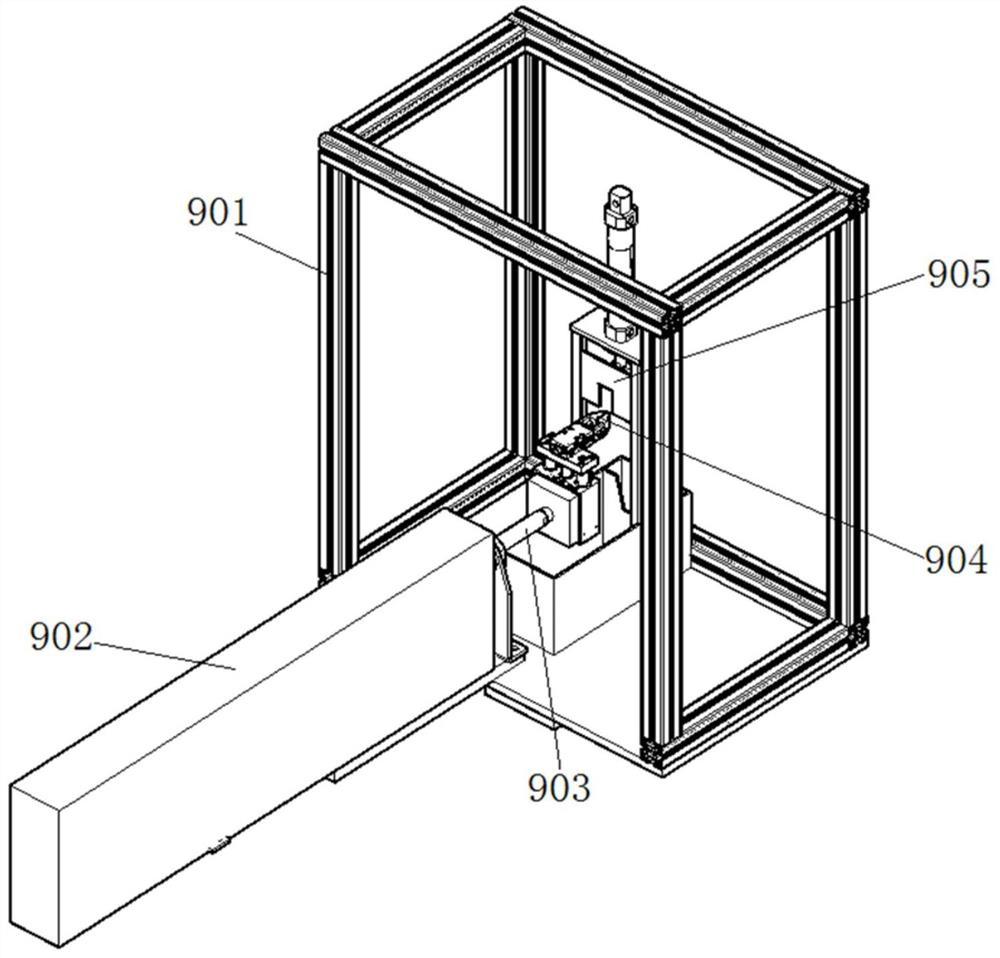
[0003] In the existing cutting and separating device for injection molded parts, the movement of the piston rod 903 in the cylinder 902 requires a longer stroke, so the length of the cylinder 902 is also longer Long, which results in a longer length of space required for the entire cutting and separation device, and a larger footprint
In addition, due to the high temperature of the injection molded parts clamped by the clamping part 904 at the receiving injection molded parts station, the rate of defective products formed after cutting the high-heat injection molded parts directly is very high, so the high-heat injection molded parts should be cooled Cutting is performed after a period of time, which leads to a long cycle of the entire cutting production process, which affects the production capacity

Method used


Image

  • Cutting separation system for injection molding part and cutting separation method of cutting separation system
  • Cutting separation system for injection molding part and cutting separation method of cutting separation system
  • Cutting separation system for injection molding part and cutting separation method of cutting separation system

Examples


Embodiment Construction

[0089] The implementation of the present invention will be illustrated by specific specific examples below, and those skilled in the art can easily understand other advantages and effects of the present invention from the contents disclosed in this specification.

[0090] Please refer to attached picture. It should be noted that the structures, proportions, sizes, etc. shown in the drawings attached to this specification are only used to match the content disclosed in the specification, for those who are familiar with this technology to understand and read, and are not used to limit the implementation of the present invention. Limiting conditions, so there is no technical substantive meaning, any modification of structure, change of proportional relationship or adjustment of size, without affecting the effect and purpose of the present invention, should still fall within the scope of the present invention. The disclosed technical content must be within the scope covered. At t...


PUM


Abstract

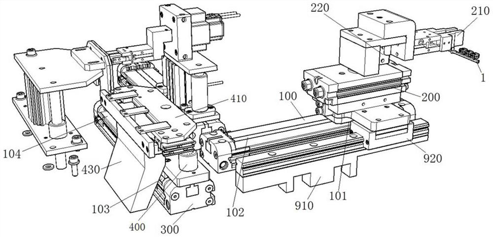
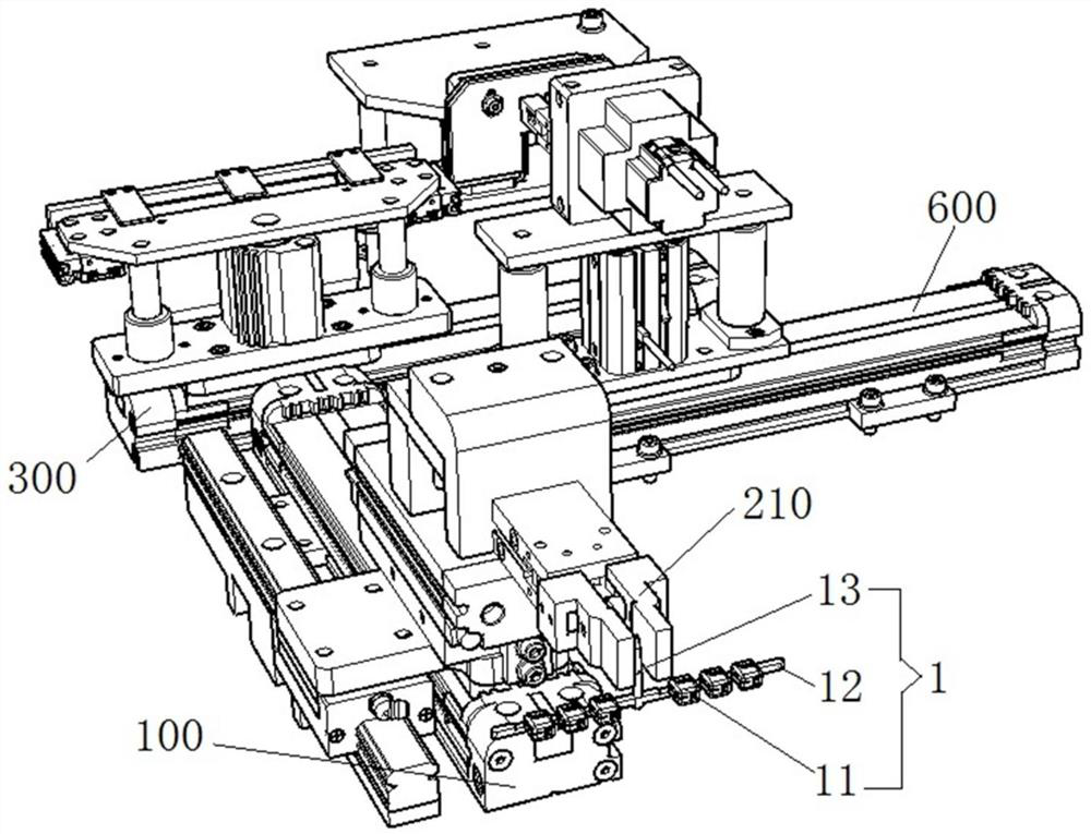
The invention provides a cutting separation system for an injection molding part and a cutting separation method of the cutting separation system. The cutting separation system comprises an input part translation driving mechanism, an input part rotating mechanism arranged on the input part translation driving mechanism, an input part clamping jaw arranged on the input part rotating mechanism, a bearing part translation driving mechanism in staggered arrangement with the input part translation driving mechanism, a bearing part lifting mechanism arranged on the bearing part translation driving mechanism, and a cutting tool; a bearing platform is arranged on the bearing part lifting mechanism, and a bearing clamping groove for placing the injection molding part is formed in the top surface of the bearing platform; and the cutting tool is used for cutting the injection molding part. The action stroke can be shortened, and the occupied area required by the system is saved; the action period is shortened, and the productivity of the system is improved; and the reject ratio of products can be effectively reduced, and the production cost is effectively reduced.

Description

technical field [0001] The invention relates to the field of cutting devices, in particular to a cutting and separating system for injection molded parts and a cutting and separating method thereof. Background technique [0002] Products are processed by injection molding process. After the injection molding of injection molded parts is completed, multiple products are generally connected to the flow channel through the glue port, and the flow channel is connected to the injection port. The product is generally cut from the injection molded part by a cutting and separating device. Such as figure 1 As shown, the existing cutting and separating device for injection molded parts includes a bracket 901, on which a cylinder 902 is installed, the piston rod 903 of the cylinder 902 is connected to the clamping part 904, the piston rod 903 moves along the horizontal direction, and the piston rod 903 Drive the clamping part 904 to reciprocate between the station for receiving injec...

Claims


Application Information

Patent Timeline
Patent Type & Authority Applications(China)
IPC IPC(8): B29C45/38
CPCB29C45/382Y02W30/62
Inventor 谢俊宏王茂昌柏建成李文由李益飞
Owner YKK ZIPPERSHENZHEN CO LTD
Why Eureka
Try Eureka