Method for transferring polymer particles among gas-phase polymerization reactors

A polymer particle, gas-phase polymerization technology, applied in chemical instruments and methods, chemical/physical processes, etc., can solve the problem that the contact time and gas velocity of the purified gas and the polymer particles cannot be adjusted, the effect of purification cannot be known, and the monitoring cannot be performed. Purification process and other problems, to achieve the effect of shortening the action cycle, simplifying the transfer steps, and increasing the transfer efficiency

Active Publication Date: 2010-12-29
CHINA PETROLEUM & CHEM CORP +1
View PDF6 Cites 0 Cited by
  • Summary
  • Abstract
  • Description
  • Claims
  • Application Information

AI Technical Summary

Problems solved by technology

[0005] The method has the following disadvantages: 1. The solid particles are transferred by a series of sequential steps of the gas-solid separator and the transfer tank, and the steps such as feeding, purging, purification, boosting, and discharging are carried out respectively, so that the cycle is increased ( About 4 minutes, embodiment 1~3 in specification), this makes gas-solid separator and transfer tank must use larger volume equipment, or multiple sets of equipment operate in parallel
The time and gas velocity of the purified gas in contact with the polymer particles cannot be adjusted, and the effect of the purification cannot be known, and the purification process cannot be monitored

Method used


Image

  • Method for transferring polymer particles among gas-phase polymerization reactors
  • Method for transferring polymer particles among gas-phase polymerization reactors

Examples


Embodiment 1

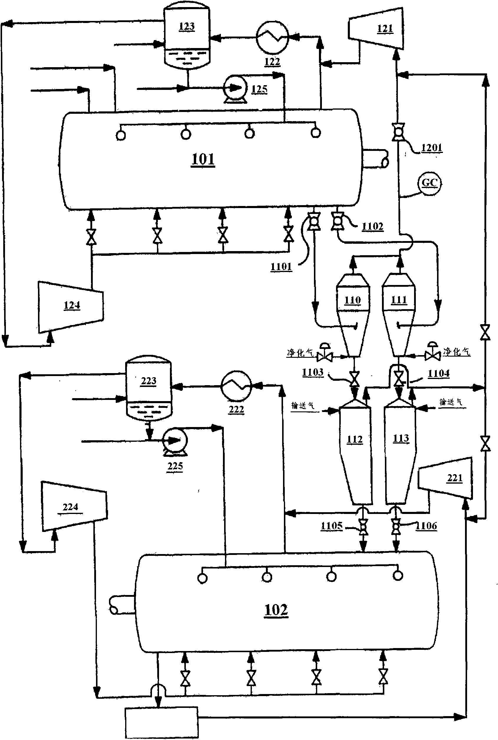
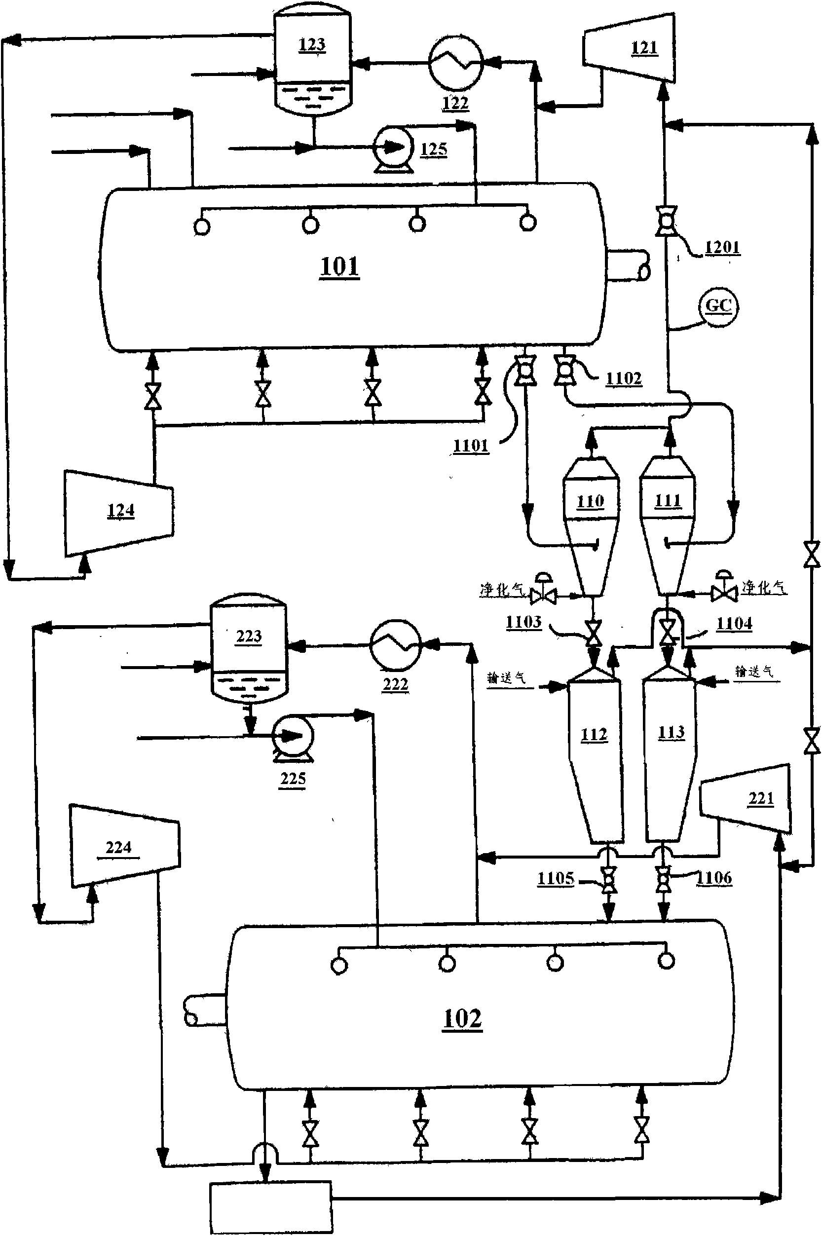
[0028] In two gas phase polymerization reactors arranged in series, propylene monomer is subjected to continuous gas phase polymerization, normally producing a solid homopolymer, with low molar content of hydrogen present in the upstream and downstream reactors. According to the present invention, only one of the two trains is used to transfer the polypropylene pellets, and a cycle time of 1 minute is used. Propylene monomer was used as purge gas, and propylene monomer was used as transport gas. The tail gas from the transfer tank is discharged to the inlet of the tail gas compressor 121 .

Embodiment 2

[0030] In two gas phase polymerization reactors arranged in series, propylene monomer is subjected to continuous gas phase polymerization, normally producing a solid homopolymer, with low molar content of hydrogen present in the upstream and downstream reactors. According to the present invention, the discharge valves 1101 and 1102 of reactor 101 use valves with adjustable openings to continuously discharge materials, instead of using pulse mode, the addition of purified gas and tail gas recovery are also carried out continuously, and only one of the two rows of equipment is used for transfer For pellets of polypropylene, a cycle time of 1 minute was used. Propylene monomer was used as purge gas, and propylene monomer was used as transport gas. The tail gas from the transfer tank is discharged to the inlet of the tail gas compressor 121 .

Embodiment 3

[0032] In two gas phase polymerization reactors arranged in series, propylene monomer is subjected to continuous gas phase polymerization, normally producing a solid homopolymer, with low molar content of hydrogen present in the upstream and downstream reactors. According to the invention, the polypropylene pellets were transferred using two trains of equipment simultaneously, using a cycle time of 1 minute. Propylene monomer was used as purge gas, and propylene monomer was used as transport gas. The tail gas from the transfer tank is discharged to the inlet of the tail gas compressor 121 .


PUM


Abstract

The invention provides a method for transferring polymer particles among gas-phase polymerization reactors, which is used for two or more gas-phase polymerization reactors connected in series, wherein the two or more gas-phase polymerization reactors connected in series continuously polymerize a polymer monomer or a mixture thereof, and each reactor contains a particle-quenching micro-fluidized bed for the polymer monomer. The transferring method shortens the cycle, simplifies the process and can effectively improve the transfer efficiency and the purification efficiency.

Description

technical field [0001] The present invention relates to a method for transferring polymer particles between gas phase polymerization reactors, and more particularly, to a process for producing olefin homopolymers or copolymers in two or more series-connected Transfer method between gas phase polymerization reactors. technical background [0002] Homopolymers and copolymers of olefins can be produced using two or more gas phase polymerization reactors arranged in series. Its process flow mainly includes process units such as catalyst preparation, polymerization reaction, reaction gas circulation, polymer degassing, steaming and drying. Many patents have described this gas phase polymerization method, including: US3,957,448, US3,965,083, US3,971,768, CN1228096A and so on. [0003] The specific process may include: usually using a high-efficiency catalyst component and a co-catalyst, preferably using a solid fourth-generation transition metal-based high-activity olefin polyme...

Claims


Application Information

Patent Timeline
Patent Type & Authority Applications(China)
IPC IPC(8): B01J8/00B01J8/26C08F2/34C08F10/00
Inventor 杨芝超仝钦宇陈江波杜亚锋刘旸
Owner CHINA PETROLEUM & CHEM CORP
Why Eureka
Try Eureka