Manufacturing process of light guide fiber illuminatormodule lamp

A technology of light guide fiber and manufacturing process, which is applied in the field of manufacturing process of light guide fiber emitter module lamps, can solve the problems of easy failure of light guide fiber fixation, deflection and deformation of pressure spring, troublesome installation and operation, etc., so as to avoid insertion The effect of fixing and fixing failure, avoiding the skew of compression spring, and making production and assembly easy and convenient

Active Publication Date: 2019-09-24
中山市景尧照明灯饰有限公司
View PDF6 Cites 0 Cited by
  • Summary
  • Abstract
  • Description
  • Claims
  • Application Information

AI Technical Summary

Problems solved by technology

[0004] 1. The fixing method between the light guide fiber and the housing is simple and rough. In order to ensure that the light guide fiber is firmly fixed, the tight clamping force of the toothpick or the high temperature of the hot melt adhesive will inevitably cause the light guide fiber to deform or even break. The light guide fiber installed in this way cannot be disassembled and cannot be reused; if in order to avoid deformation or breakage of the light guide fiber, use a looser clamping force of a toothpick or a lower temperature of the hot melt adhesive, which will affect the connection between the light guide fiber and the housing. The reliability of the fixed connection between them, especially in the transportation vibration, the fixing of the light guide fiber is very easy to fail; moreover, the fixation of each light guide fiber on the housing requires toothpicks or hot melt glue, which is very troublesome to operate. It requires a lot of labor, which is not conducive to cost control; and hot melt adhesive heating will produce a pungent smell, which is not conducive to environmental protection;
[0005] 2. Multiple light guide fibers correspond to the same light emitter, and each light guide fiber needs to go from the light emitter to the mounting hole of the housing, the length of which is long and the material cost is high; such multiple light guide fibers correspond to the same light emitter, Affected by the caliber of the light emitter and the angle of light emission, the distribution of brightness derived from the light guide fiber is uneven; and the connection between the light guide fiber and the light emitter requires the rear ends of multiple light guide fibers to be aggregated together and cut at the same head. It will produce a pungent smell of smoke, which is not conducive to environmental protection and the health of the people present;
[0006] 3. The shell is bulky, heavy, and easy to break, which is not only inconvenient for transportation and installation, but also not conducive to cost control and environmental protection; if the whole is assembled in the factory and directly transported to the site for installation, a large number of wooden strips will be used for transportation packaging It is not only bulky and heavy, but also not conducive to environmental protection; moreover, the optical fiber will be bent, bent, and broken to varying degrees during transportation, and the deformation and damage rate is high, which affects the overall appearance; moreover, the wood material The installation of the shell requires another keel frame, which is cumbersome to install and the cost is high
Using the technology provided by this patent document, although the installation of the light guide fiber is simpler, the installation of the pressure spring, the clip and the lock is troublesome: in order to facilitate the installation of the pressure spring, it is necessary to set up enough installation space, a larger installation space The pressure spring is prone to deflection and deformation, especially the insertion and extraction of the light guide fiber will inevitably cause the deflection and deformation of the pressure spring, which will eventually lead to the failure of the clamp to fix the light guide fiber; and, this technology uses the same The light source is supplied through the light guide tube, which still cannot avoid the problem of uneven brightness of the light guide tube at different positions, which also increases the volume of the lamp and takes up a large installation space

Method used


Image

  • Manufacturing process of light guide fiber illuminatormodule lamp
  • Manufacturing process of light guide fiber illuminatormodule lamp
  • Manufacturing process of light guide fiber illuminatormodule lamp

Examples


Embodiment 1

[0040] A manufacturing process of a light guide fiber emitter module lamp, comprising the following steps:

[0041] Step 1: Assemble the shell, light source board and lock core into a module;

[0042] Step 2: Insert the light guide fiber into the corresponding lock core, and assemble it into a modular light.

[0043] The structure of the module lamp is as follows:

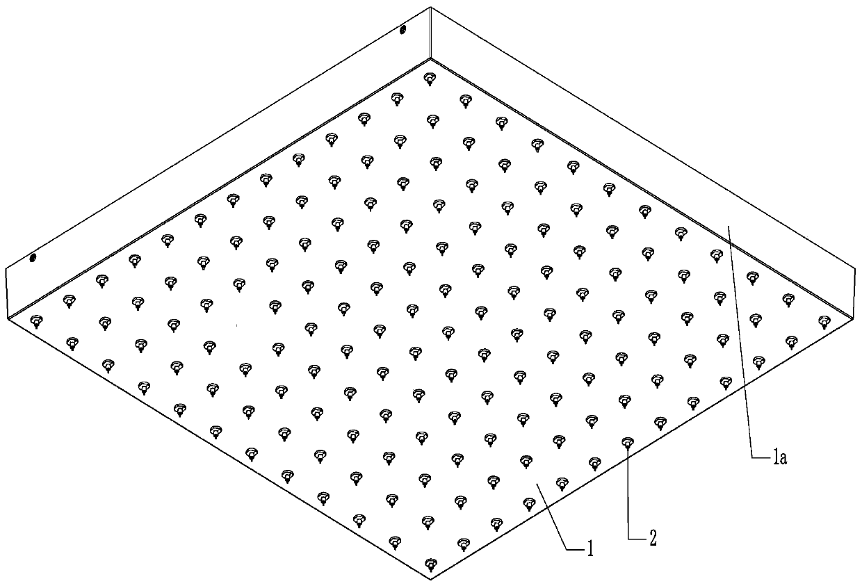
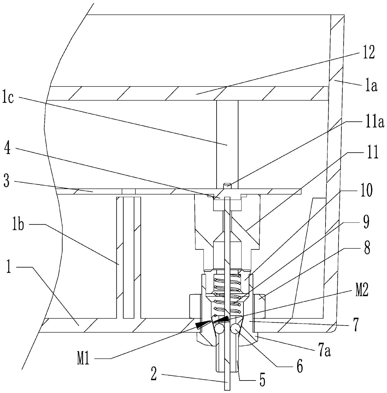
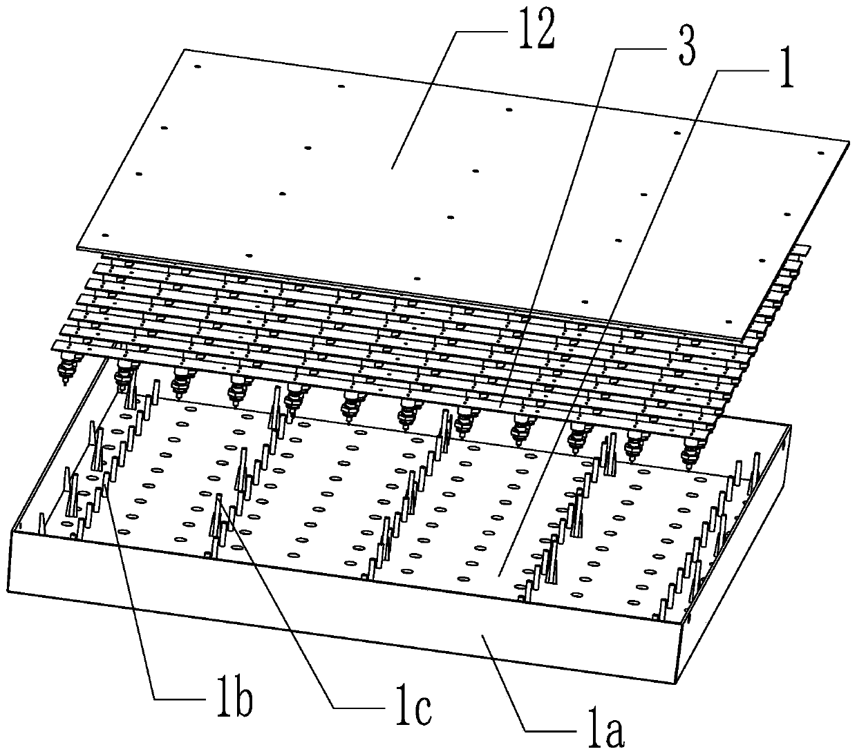
[0044] Such as figure 1 and image 3 As shown, it includes a casing 1 and at least one light source board 3, at least one installation hole 1d is opened on the casing 1, and light sources 4 corresponding to the installation holes 1d are provided on the light source board 3. The shape of the housing 1 is not limited, and may be rectangular, circular or other shapes. The edge of the shell 1 extends inward to form a shroud 1a, so that the shell 1 is in the shape of a box with an opening, and the shell 1 in this embodiment is in a square shape. The inner wall of the housing 1 protrudes to form at least one mounti...

Embodiment 2

[0052] Such as Figure 4 and Figure 5 As shown, in this embodiment, the first locking frame 11 extends toward one end of the conduit 10 to form a tube portion 11 b that accommodates the conduit 10 and the inner end of the first locking cup 7 . The shell 1 is in the shape of a strip. Other technical features of this embodiment are the same as those of Embodiment 1, and will not be repeated here.

Embodiment 3

[0054] Such as Figure 6 and Figure 7 As shown, the positioning assembly includes a mounting tube 1e formed by a protrusion on the inner wall of the housing 1, and a second locking cup 13 and a second locking frame 14 are installed in the mounting tube 1e, and the second locking cup 13 Located between the second locking frame 14 and the inner wall of the housing 1 , the first tapered surface M1 is located in the second locking cup 13 . The inner end of the second locking frame 14 is in contact with the light source board 3, and at the end of the second locking frame 14 facing the second locking cup 13, a guide hole with a large outside and a small inside is provided. The compression spring 9 snapped into the guide hole. On the end of the second locking frame 14 facing the light source board 3 , there is a through hole through the guide hole to make way for the light guide fiber 2 , and the inner end of the through hole is thickened to make way for the light source 4 . The ...


PUM


Abstract

The invention discloses a manufacturing process of a light guide fiber illuminator module lamp. Firstly a shell, a light source board and a lock catch core are assembled into a module; then a light guide fiber is inserted into the corresponding locking core to assemble the module lamp; the module lamp includes a shell and a light source plate, mounting holes are formed in the shell, light sources corresponding to the mounting holes one by one are arranged on the light source plate, fixed light guide fibers are inserted on the mounting holes through the lock catch core, the inner ends of the light guide fibers obtain light from a corresponding light source, the lock catch core includes a lock catch tube, a lock catch bead, a compression spring, and a positioning assembly with a through hole and fixed to the shell, a first conical surface with the small outside and the large inside is arranged at the end, near the mounting holes, of the through hole, the outer wall of the inner end of the latch catch tube is a second conical surface matched with the first conical surface, one or more lock catch beads are mounted in the second conical surface part at the inner end of the lock catch tube in a clamping mode, the compression spring is placed under the inner end of the lock catch tube, thus plug and play of the light guide fiber is realized, and reliability and stability of light guide fiber mounting are effectively improved.

Description

technical field [0001] The invention belongs to the technical field of lamps, and in particular relates to a manufacturing process of a light guide fiber emitter module lamp. Background technique [0002] At present, with the advancement of technology, LED fiber optic lamps are becoming more and more popular, and their applications in the field of architectural decoration are becoming more and more extensive. Traditional architectural decoration LED fiber optic decorative lamps mainly use wooden boards pasted with mirror panels or sound-absorbing cotton as the shell, and the shell is punched to insert light-guiding fibers, and the rear ends of multiple light-guiding fibers are connected to a light emitter. The description of the patent document CN202650262U is attached figure 2 In , the way of traditional light guide fiber to obtain light source is given. Moreover, the light guide fiber of the traditional architectural decoration LED optical fiber decorative lamp is fixed ...

Claims


Application Information

Patent Timeline
Patent Type & Authority Applications(China)
IPC IPC(8): F21S2/00F21V15/01F21V8/00F21V19/00F21V17/16
CPCF21S2/005F21V15/01F21V17/164F21V19/00F21V2200/10
Inventor 罗力程
Owner 中山市景尧照明灯饰有限公司
Why Eureka
Try Eureka