
A Brillouin Scattering Signal Denoising Method Based on Spectrum Center Alignment

A technology of Brillouin scattering and Brillouin frequency shift, used in image enhancement, instrumentation, and optical devices to transmit sensing components, etc., can solve the problem of increasing computational complexity, distortion of temperature or strain information, and reducing processing speed, etc. problem, to reduce computational complexity, improve efficiency and quality, and avoid boundary blurring

Active Publication Date: 2020-06-09
NANJING UNIV OF AERONAUTICS & ASTRONAUTICS
View PDF9 Cites 0 Cited by
  • Summary
  • Abstract
  • Description
  • Claims
  • Application Information

AI Technical Summary

Problems solved by technology

[0006] For example, using wavelet denoising (Farahani M A, Wylie M T V, Castillo-Guerra E, et al. Reduction in the number of averages required in BOTDA sensors using wavelet denoising techniques[J]. Journal of Lightwave Technology, 2011, 30(8): 1134- 1142.) can achieve the above purpose, but because the filtering operation is performed on the whole image in the transform domain, the detailed information in the spatial domain will be lost, and it is difficult to deal with the image formed by the Brillouin frequency shift mutation caused by the temperature or strain mutation edge, which eventually deteriorates the spatial resolution of the sensing system
[0007] Denoising methods other than wavelet denoising usually also compromise the spatial resolution of the sensing, causing distortion of temperature or strain information
And when dealing with large temperature or strain changes, some methods require larger masks, which increases computational complexity, increases computational overhead, and reduces processing speed

Method used


Image

  • A Brillouin Scattering Signal Denoising Method Based on Spectrum Center Alignment
  • A Brillouin Scattering Signal Denoising Method Based on Spectrum Center Alignment
  • A Brillouin Scattering Signal Denoising Method Based on Spectrum Center Alignment

Examples


Embodiment Construction

[0033] The present invention is described in further detail now in conjunction with accompanying drawing.

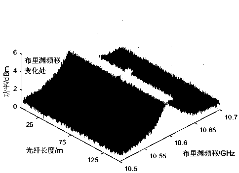
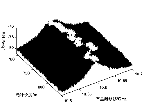
[0034] The average Brillouin scattering spectrum of 256 times to be processed is as follows image 3 As shown, the fiber length of this section is 150 meters, there are 300 data sampling positions along the fiber axis, the sampling interval is 0.5 meters, 200 frequency points are obtained at each fiber position, the sampling interval is 1Mhz, and the frequency range is from 10.5GHz to 10.7GHz. The Brillouin spectrum signal of this figure contains a total of 200×300 data points. in Figure 4 It is the noise-free control group of this group of data. The converted two-dimensional grayscale image of the Brillouin scattering spectrum with 256 average times is as follows: Figure 5 shown. Figure 6 is a 2D grayscale image of the noise-free control group.

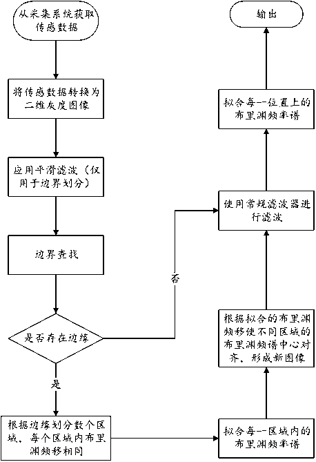
[0035] like figure 2 As shown, for the Brillouin spectrum signal, the present invention performs denoising process...


PUM


Abstract

The present invention provides a Brillouin scattering signal denoising method based on spectrum center alignment. The steps are as follows: 1) Convert the Brillouin spectrum signal collected by the Brillouin optical time domain sensing system into a two-dimensional grayscale image ; 2) Smooth filtering of the two-dimensional grayscale image; 3) Use edge detection to obtain the position where the Brillouin frequency shift changes sharply, and divide the image into different areas along the fiber axis; 4) Obtain the Brillouin frequency of each area Frequency shift position; translate each area to align the Brillouin spectrum centers of different areas to obtain a new image; 5) filter the new image, and move each area in the opposite direction after denoising is completed; 6) fit each position The Brillouin frequency spectrum on the fiber can be used to obtain the Brillouin frequency shift information along the entire sensing fiber, and the temperature and strain distribution information on the fiber can be obtained. The denoising method of the present invention can avoid boundary blurring, enhance the denoising effect, reduce the size of the filter window, and reduce the computational complexity.

Description

technical field [0001] The invention belongs to the technical field of optical fiber sensing, and in particular relates to a Brillouin scattering signal denoising method based on frequency spectrum center alignment. Background technique [0002] The demand for continuous distributed monitoring of temperature and strain is very extensive, and many fields such as energy, electric power, and construction use it as a means of fault diagnosis and accident warning. The pressure loads of various pipelines, the settlement changes of building structures, and the temperature changes of oil depot tank farms all need to be discovered and quickly located. The Brillouin distributed optical fiber sensing system has a simple structure and is easy to build and implement measurements in various application environments. [0003] The Brillouin scattering distributed optical fiber sensing system usually consists of sequentially connected lasers, optical modulators, optical amplifiers, optical ...

Claims


Application Information

Patent Timeline
Patent Type & Authority Patents(China)
IPC IPC(8): G01D5/353G01D21/02G06T5/00
CPCG01D5/35354G01D21/02G06T5/70
Inventor 路元刚张宇阳彭楗钦
Owner NANJING UNIV OF AERONAUTICS & ASTRONAUTICS
Learn More