
Method and device for determining lateral motion stability of high-speed train

A technology for high-speed trains and lateral movement, applied in railway vehicle testing, etc., can solve the problems of inconsistency, no reflection, and inability to generalize the evaluation methods of lateral motion stability, etc., and achieve the effect of accurate evaluation

Active Publication Date: 2019-09-24
CHINA RAILWAYS CORPORATION +2
View PDF5 Cites 9 Cited by
  • Summary
  • Abstract
  • Description
  • Claims
  • Application Information

AI Technical Summary

Problems solved by technology

At present, the evaluation methods for the lateral motion stability of high-speed trains at home and abroad are not unified. The existing evaluation methods for the lateral motion stability of high-speed trains in my country still use the evaluation indicators and limit values ​​of ordinary speed trains, while the operating environment and line of high-speed trains Conditions, wheel-rail profiles, and vehicle structural parameters are obviously different from ordinary-speed trains. Therefore, the evaluation methods for the lateral motion stability of high-speed trains and ordinary-speed trains cannot be generalized. In addition, the operating environment of high-speed trains in service is complex and changeable. Stability is very sensitive to initial conditions such as wheel-rail nonlinearity and line disturbance. The inventor found in the process of implementing the embodiment of the present invention that: the stability of the lateral motion of the high-speed train is related to the bifurcation form of the limit cycle of the train hunting instability and the vehicle hunting failure. However, the prior art does not reflect the bifurcation form of the limit cycle of the above-mentioned train hunting instability and the evaluation index of the vehicle hunting instability frequency

Method used


Image

  • Method and device for determining lateral motion stability of high-speed train
  • Method and device for determining lateral motion stability of high-speed train
  • Method and device for determining lateral motion stability of high-speed train

Examples


Embodiment Construction

[0031] In order to make the purpose, technical solutions and advantages of the embodiments of the present invention clearer, the technical solutions in the embodiments of the present invention will be clearly and completely described below in conjunction with the drawings in the embodiments of the present invention. Obviously, the described embodiments It is a part of embodiments of the present invention, but not all embodiments. Based on the embodiments of the present invention, all other embodiments obtained by persons of ordinary skill in the art without creative efforts fall within the protection scope of the present invention.

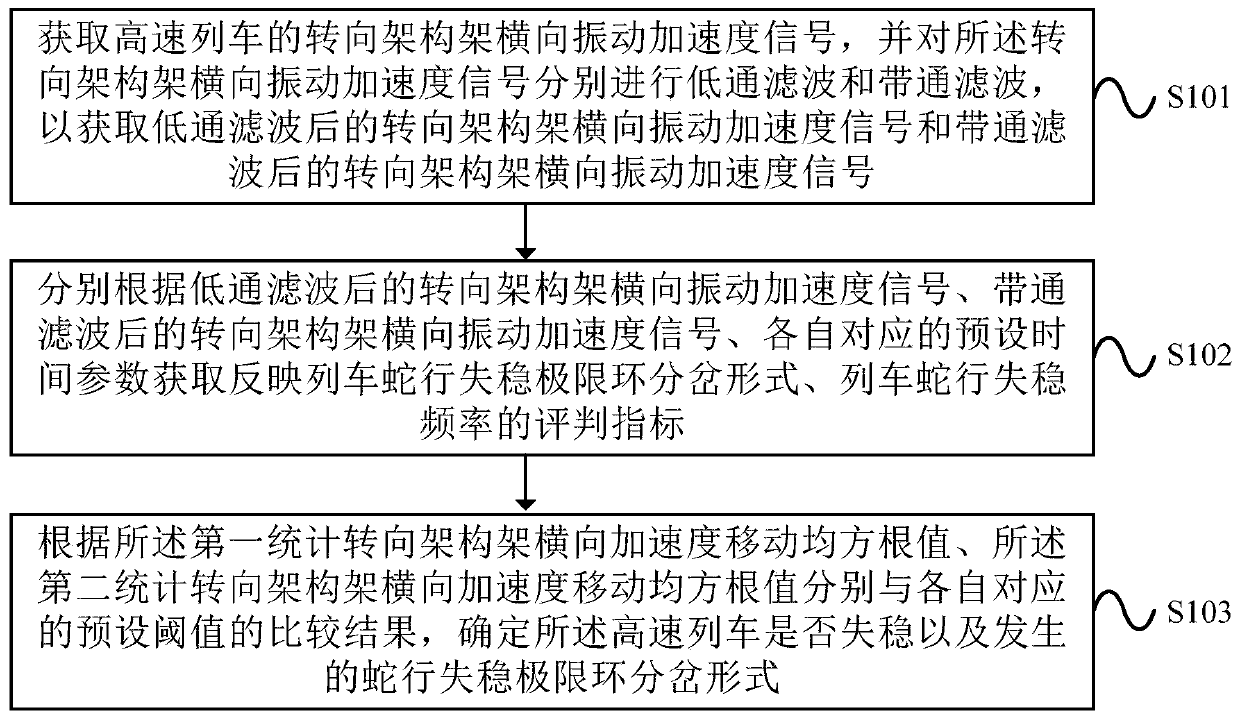
[0032] figure 1 For the present invention judges the method embodiment flow chart of high-speed train lateral movement stability, as figure 1 As shown, a method for evaluating the lateral motion stability of a high-speed train provided in the embodiment of the present invention includes the following steps:

[0033] S101: Obtain the lateral vibr...


PUM


Abstract

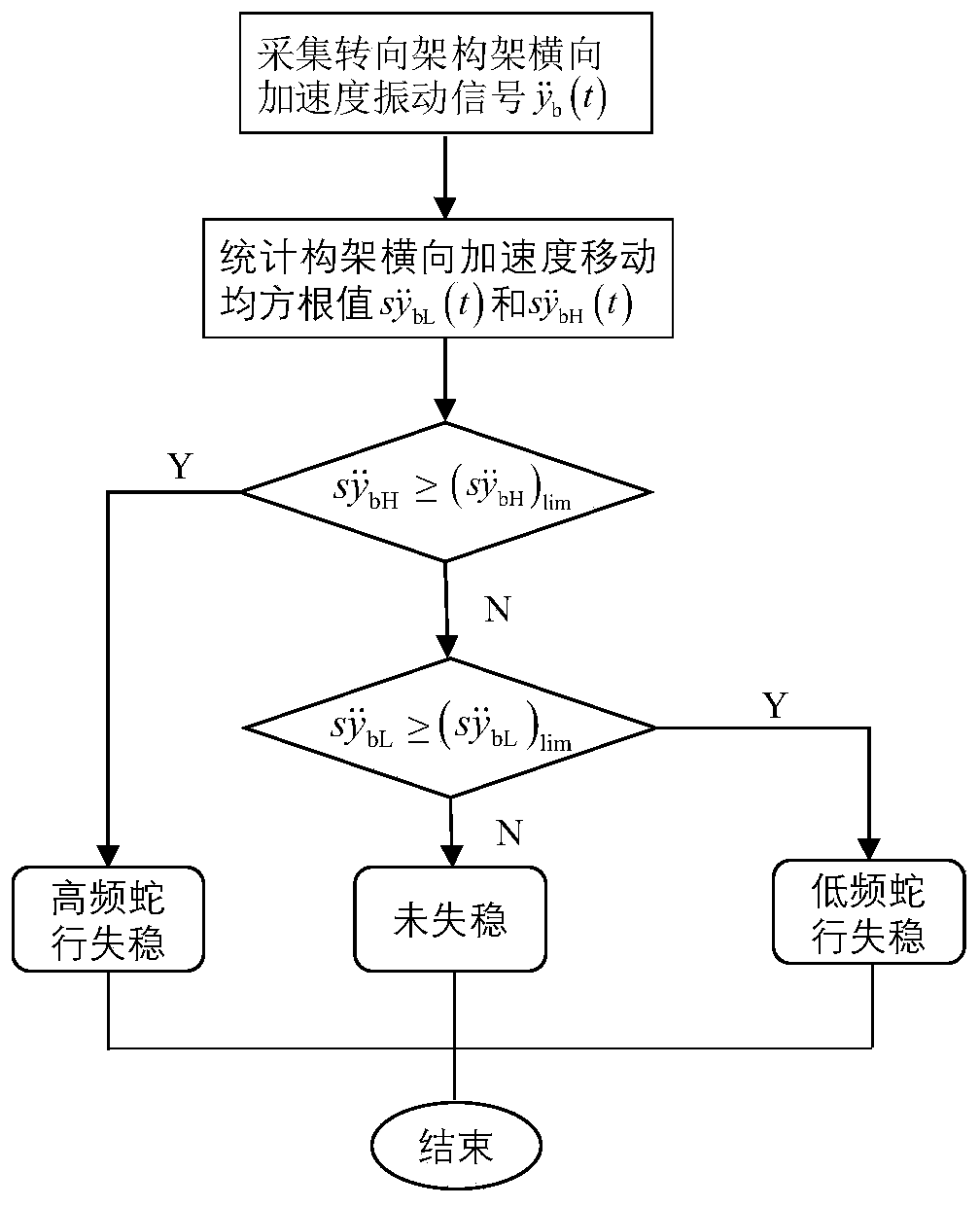
The embodiment of the invention provides a method and device for determining the lateral motion stability of a high-speed train, the method comprising the steps of: obtaining a bogie frame lateral vibration acceleration signal of the high-speed train, low-pass filtering and band-pass filtering the bogie frame lateral vibration acceleration signal separately, and obtaining a determining index according to the low-pass filtered bogie frame lateral vibration acceleration signal, the band-pass filtered bogie frame lateral vibration acceleration signal, and respective corresponding preset time parameters; determining whether the high-speed train is instable or generates a hunting instability limit cycle bifurcation form based on the comparison of a first statistical bogie frame lateral acceleration movement root-mean-square value and a second statistical bogie frame lateral acceleration movement root-mean-square value with the respective preset threshold values. The device executes the above method. The method and device provided by the embodiment of the present invention can accurately determine the lateral motion stability of the high-speed train.

Description

technical field [0001] The invention relates to the technical field of train safety, in particular to a method and device for evaluating the lateral motion stability of a high-speed train. Background technique [0002] Snaking motion is a special form of train movement. When the running speed of the train exceeds a certain value and the external excitation is large enough, the snaking motion of the train will diverge, the train system will lose the stability of lateral motion, and the vibration amplitude of each component of the train will will increase significantly, and the dynamic performance of the train will deteriorate sharply, which will affect the ride comfort and even endanger the driving safety in severe cases. Therefore, how to scientifically and reasonably judge the lateral motion stability of high-speed trains (trains with a speed of more than 200 km / h) during service is an urgent problem to be solved in my country at this stage, and it is also an important guar...

Claims


Application Information

Patent Timeline
IPC IPC(8): G01M17/08
CPCG01M17/08
Inventor 孙丽霞蔡园武侯茂锐周春阳常崇义
Owner CHINA RAILWAYS CORPORATION
Learn More