Auxiliary structure of atmospheric pollution data acquisition device employing unmanned aerial vehicle

A data acquisition and auxiliary structure technology, applied in the direction of measuring devices, electrical components, aircraft parts, etc., can solve problems such as damage, device collision, device damage, etc., to achieve the effect of ensuring accuracy, enhancing connection, and avoiding shaking

Inactive Publication Date: 2019-09-24
郑刚
View PDF11 Cites 5 Cited by
  • Summary
  • Abstract
  • Description
  • Claims
  • Application Information

AI Technical Summary

Problems solved by technology

[0004] The purpose of the present invention is to provide an auxiliary structure of an air pollution data acquisition device of an unmanned aerial vehicle. In order to overcome the auxiliary structure of the above-mentioned existing air pollution data acquisition device of an unmanned aerial vehicle, the air pollution data acquisition device and the unmanned In the actual air pollution detection process, it is not convenient to control the UAV, and the accuracy of data collection cannot be guaranteed; at the same time, in the high altitude, the connection between the air pollution data collection device and the UAV is in the high air flow Under the influence of the drone, it is easy to shake, which increases the difficulty of operation for the operators on the ground, and at the same time causes slow data collection and is prone to damage caused by collisions between devices; among them, if an accident occurs during the use of the drone, it will be damaged. The air pollution data collection device and the UAV fall from a high altitude, resulting in damage to the device, and the air pollution data collection device and the UAV are both expensive, and the damage will increase the cost of air pollution data collection.

Method used


Image

  • Auxiliary structure of atmospheric pollution data acquisition device employing unmanned aerial vehicle
  • Auxiliary structure of atmospheric pollution data acquisition device employing unmanned aerial vehicle
  • Auxiliary structure of atmospheric pollution data acquisition device employing unmanned aerial vehicle

Examples


Embodiment Construction

[0033] The technical solutions of the present invention will be clearly and completely described below in conjunction with the embodiments. Apparently, the described embodiments are only some of the embodiments of the present invention, not all of them. Based on the embodiments of the present invention, all other embodiments obtained by persons of ordinary skill in the art without creative efforts fall within the protection scope of the present invention.

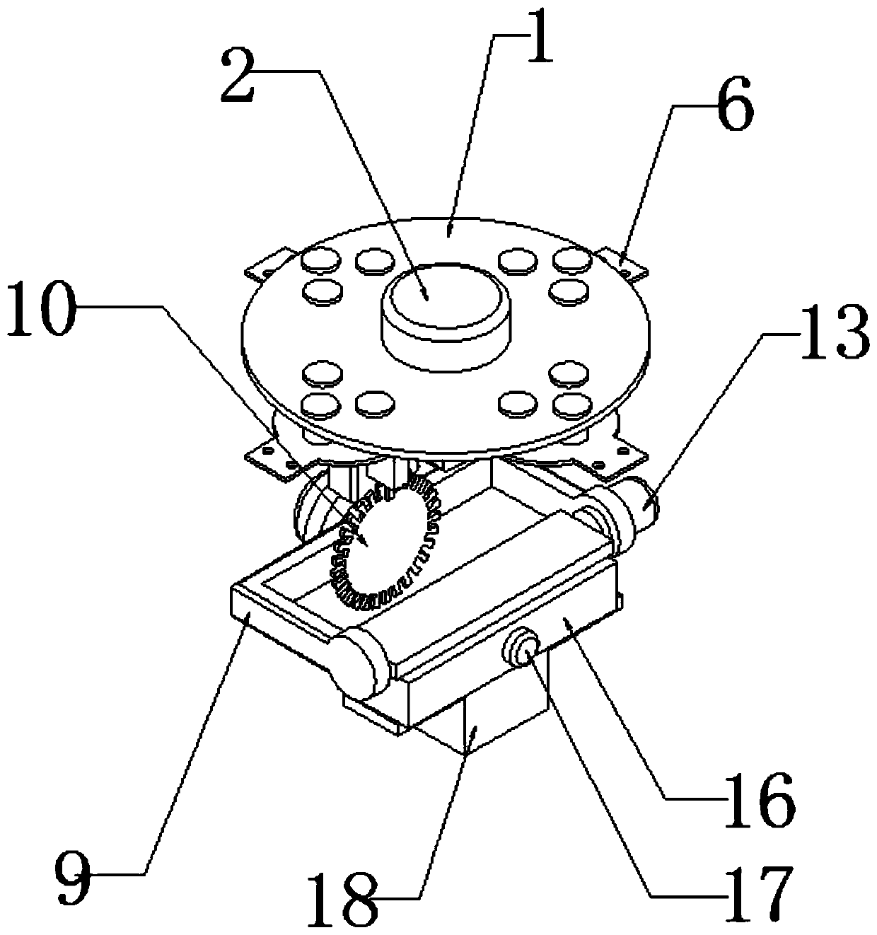
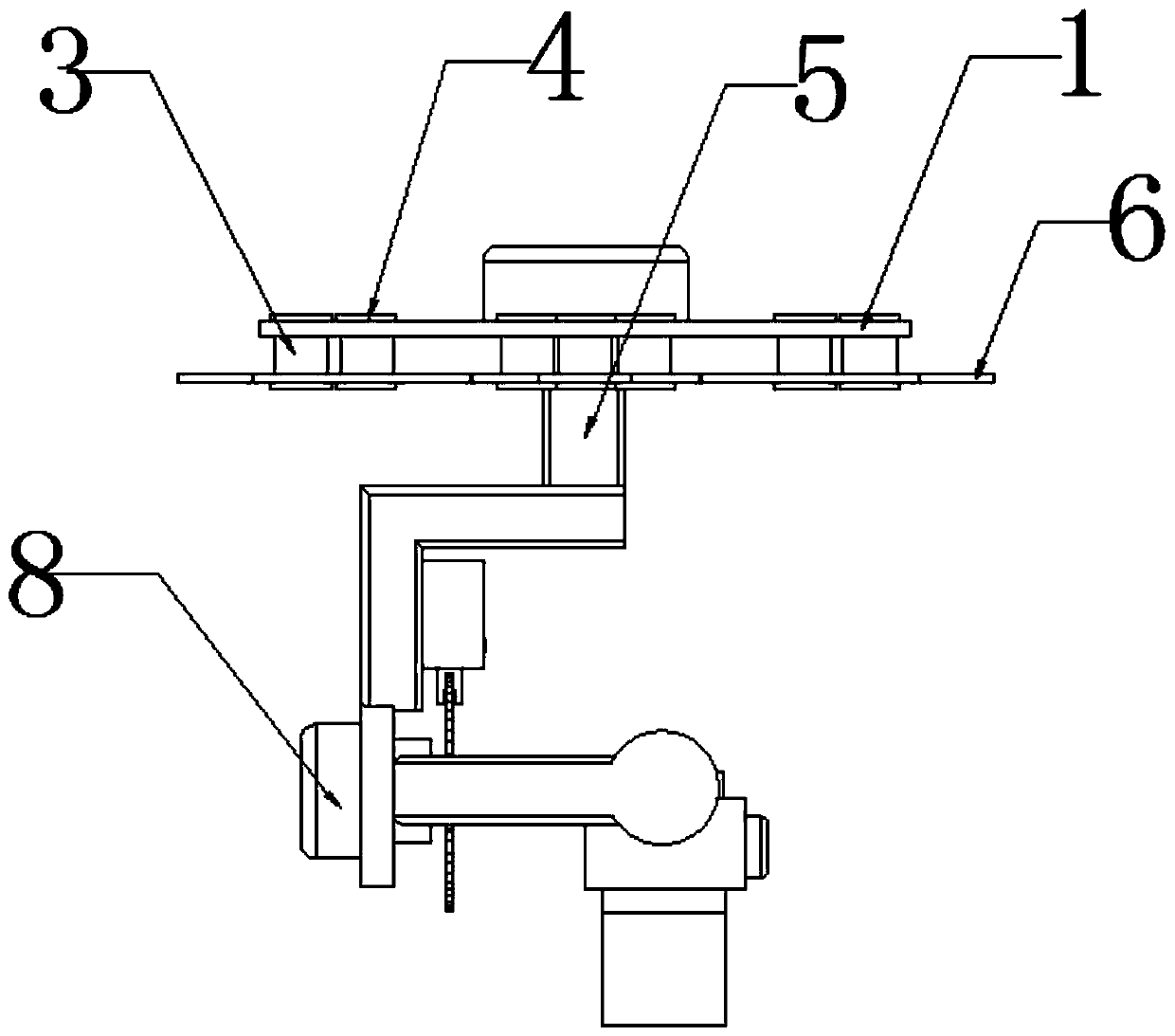
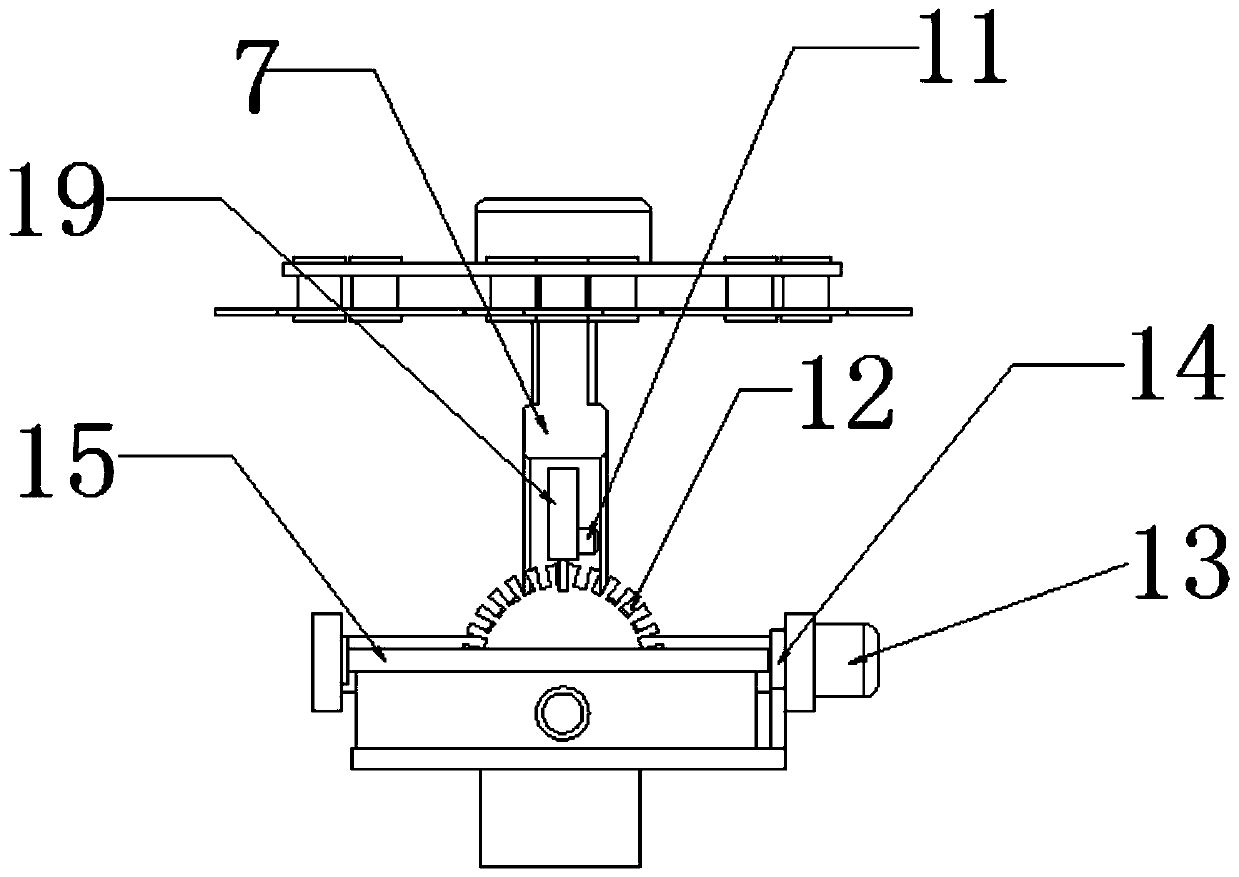
[0034] see Figure 1-5 As shown, an auxiliary structure of an air pollution data acquisition device for an unmanned aerial vehicle includes a bearing platform 1, a first servo motor 2, a connection turntable 7, a second servo motor 8, a connection turn seat 9, a third servo motor 11, The fourth servo motor 13 and the protection mechanism 18, the bottom side of the bearing platform 1 is fixedly installed by several shock-absorbing balls 3 and several installation platforms 6, the first servo motor 2 is installed at the center ...


PUM


Abstract

The invention discloses an auxiliary structure of an atmospheric pollution data acquisition device employing an unmanned aerial vehicle. The structure comprises a bearing table, a first servo motor, a connecting rotary table, a second servo motor, a connecting rotary seat, a third servo motor, a fourth servo motor and a protection mechanism. The bottom side of the bearing table is fixedly mounted with a plurality of mounting tables through a plurality of damping balls; the first servo motor is installed at the center of the top side of the bearing table, an adapter column is installed at the output end of the first servo motor and located below the bearing table, the connecting rotary table is installed at the bottom end of the adapter column, and the second servo motor is installed at one side of the bottom end of the connecting rotary table. According to the invention, the structure can achieve the determining of the atmospheric collection position and the observation of the driving of the unmanned aerial vehicle. The all-directional matched rotation can guarantee that the unmanned aerial vehicle can be conveniently controlled by an operator in the atmospheric pollution detection process through, and meanwhile, the data collection can be carried out on atmospheric pollution in all directions, so that the accuracy of the collected data is ensured.

Description

technical field [0001] The invention relates to the field of air pollution collection and detection, in particular to an auxiliary structure of an air pollution data collection device for an unmanned aerial vehicle. Background technique [0002] Among the many environmental challenges, air pollution affects the hearts of the general public. Whether it is the smog in the north or industrial waste gas emissions, it has really affected people's daily life and physical and mental health. To win the battle against air pollution, we must Accurately locating the source of pollution, at this time, the role of drones is reflected; traditional atmospheric monitoring generally adopts the method of deploying monitoring devices at fixed points, but air pollution involves a wide range, the gas composition is relatively complex, and it is easy to flow and spread. It is often difficult to obtain monitoring data quickly, in real time, and accurately, and to identify the direct source of poll...

Claims


Application Information

Patent Timeline
Patent Type & Authority Applications(China)
IPC IPC(8): G01N33/00G05B19/05H04N5/225B64D47/08
CPCG01N33/0004G05B19/054B64D47/08H04N23/00
Inventor 程晓晖陈国达
Owner 郑刚
Why Eureka
Try Eureka