Nh-fuse load break switch

A circuit breaker and fuse technology, which is applied in the field of NH fuse load circuit breakers, can solve the problems of large housing and a large amount of installation space, and achieve the effect of reducing volume, space or structure space

Active Publication Date: 2019-09-24
维纳尔电气系统有限公司
View PDF10 Cites 0 Cited by
  • Summary
  • Abstract
  • Description
  • Claims
  • Application Information

AI Technical Summary

Problems solved by technology

Therefore, conventional load-break switches have relatively large housings and correspondingly require a lot of installation space or space during their assembly, for example in switchboards

Method used


Image

  • Nh-fuse load break switch
  • Nh-fuse load break switch
  • Nh-fuse load break switch

Examples


Embodiment Construction

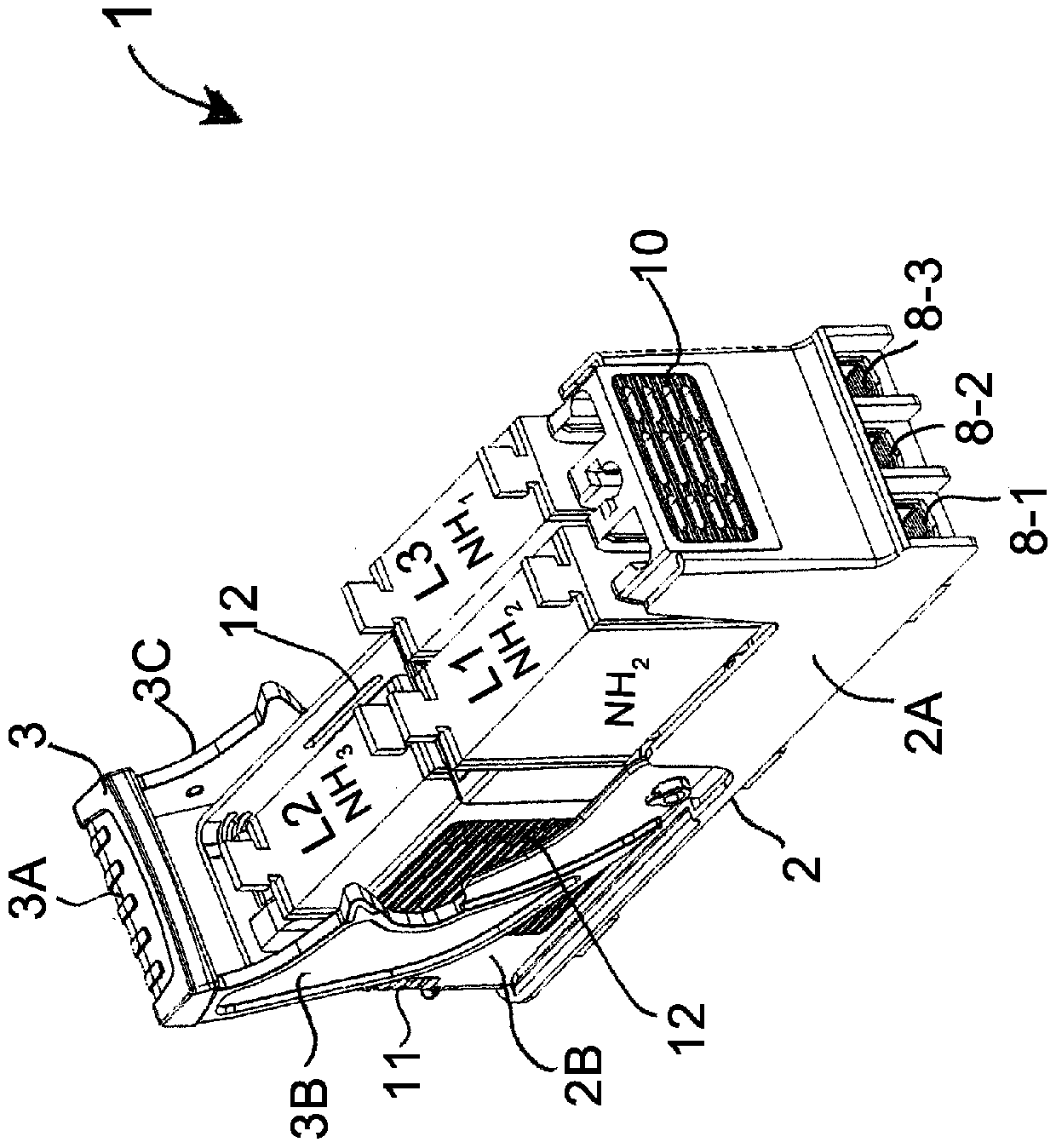
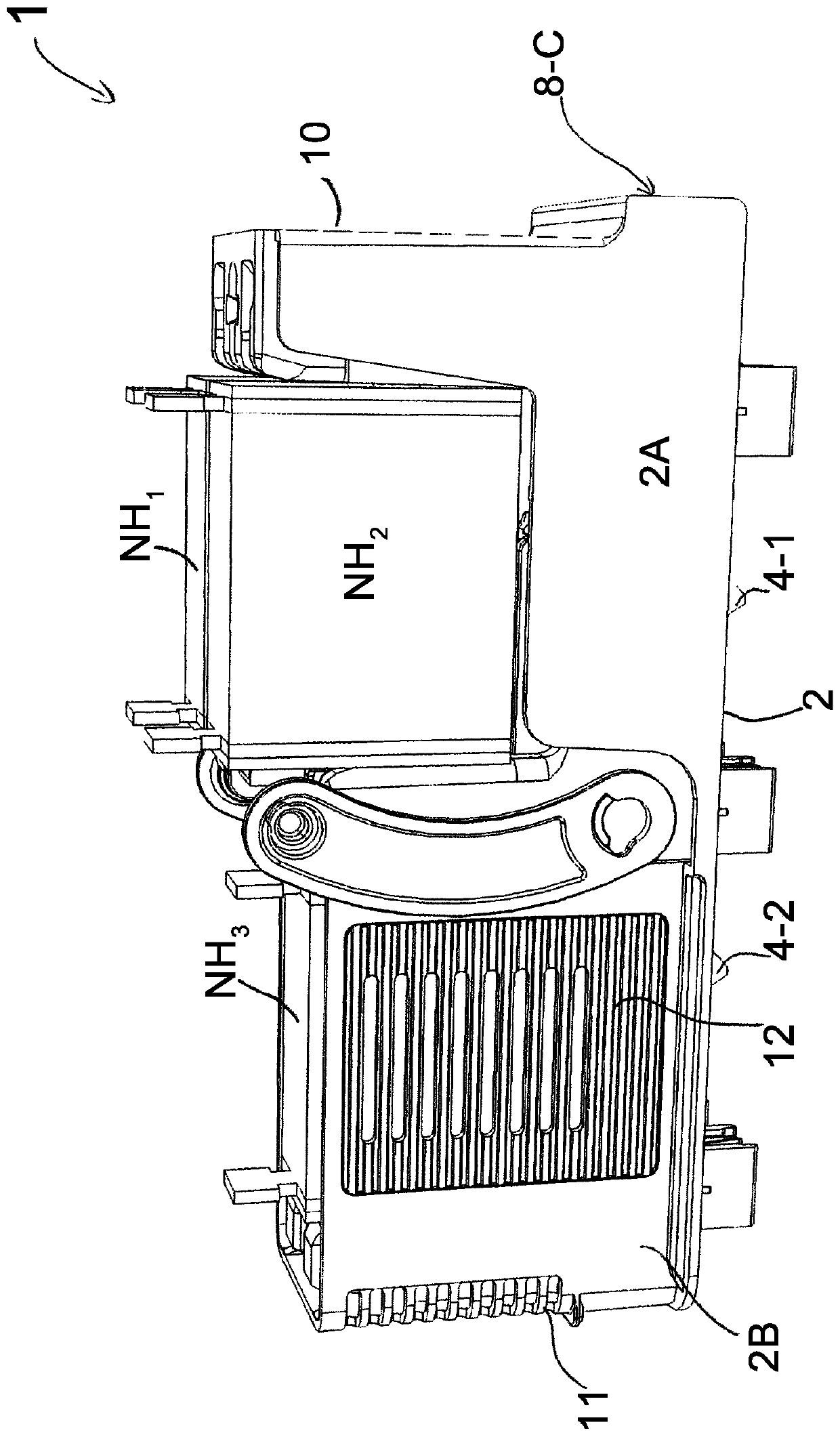
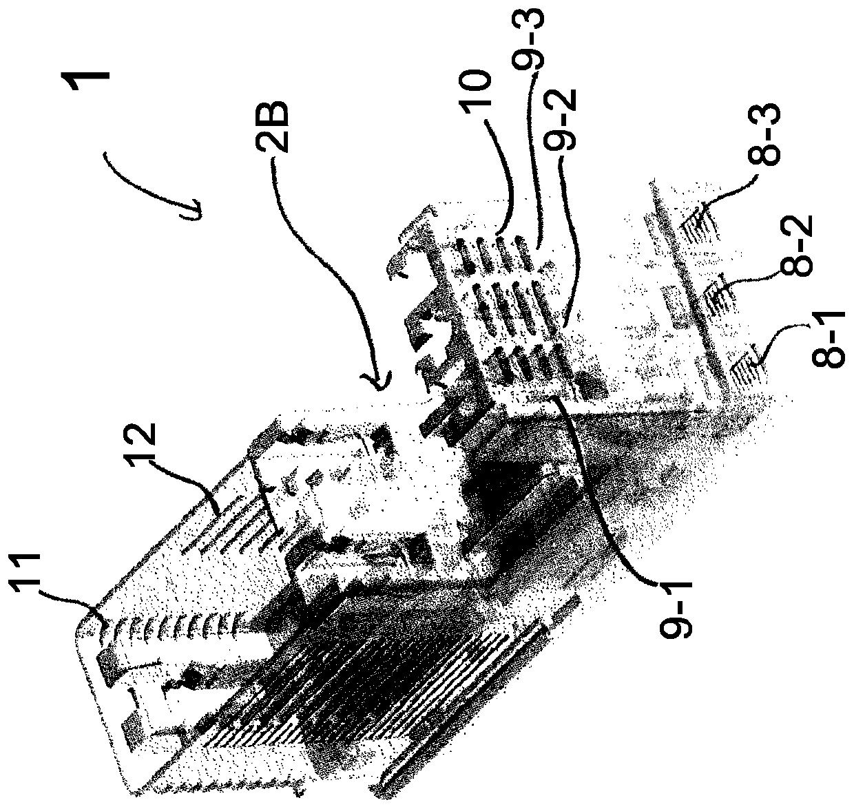
[0039] figure 1 According to the invention an embodiment of an NH-fuse load-break switch 1 according to the invention is shown. NH fuse load break switch or load break switch 1 set for multiple NH fuses. The load disconnect switch 1 has a housing 2 . The housing 2 is preferably composed of two parts and comprises a lower part 2A and a contact holder 2B. In a preferred embodiment, the contact holder 2B consists of a thermally conductive plastic. The housing 2 of the load break switch 1 is used to accommodate a plurality of NH fuses. For this purpose, the preferred setting is as image 3 The thermally conductive contact carrier 2B is shown. In the illustrated embodiment, the housing 2 of the load break switch 1 contains three NH fuses NH1 , NH2 , NH3 for three different current phases L1 , L2 , L3 . The NH fuse load break switch 1 can be assembled to a current carrying rail, especially a bus bar. In the assembled state, the housing 2 of the load-break switch 1 is preferab...


PUM


Abstract

An NH-fuse load break switch (1) has a housing (2) for receiving a plurality of NH fuses, wherein the NH fuses are vertically arranged in an assembled state, and waste heat generated by the NH fuses located in the shell (2) is diffused upwards from the shell (2) to the environment through convection in the shell (2) by passing through the NH fuses arranged above the shell (2) on the side face.

Description

technical field [0001] The present invention relates to an NH fuse load break switch for NH fuses with high power density. Background technique [0002] A load break switch is used to disconnect loads or consumers or devices from current or voltage distribution systems. A current distribution system may consist of one or more power rails, specifically bus bars. Consumers or loads are connected to the current distribution system via load break switches. Load break switches may contain pluggable fuses, especially NH fuses. To disconnect a current phase from a load or consumer, the user or operator manually manipulates the handle to disconnect the switch contacts within the load break switch. [0003] A large amount of waste heat or exotherm is generated by the NH fuse located in the housing of the NH fuse load break switch. Therefore, conventional load-break switches have a relatively large housing and correspondingly require a lot of installation space or space during the...

Claims


Application Information

Patent Timeline
Patent Type & Authority Applications(China)
IPC IPC(8): H01H85/055H01H85/143H01H85/22H01H85/47
CPCH01H85/055H01H85/143H01H85/22H01H85/47H01H2085/0555H01H9/52H01H31/122
Inventor 菲利普·施泰因贝格尔胡贝特·伦克尔约拉姆·马塞尔克里斯托弗·库尔特
Owner 维纳尔电气系统有限公司
Why Eureka
Try Eureka