nh fuse load break switch

A circuit breaker and fuse technology, which is applied in the field of NH fuse load circuit breaker, can solve the problems of large installation space and large casing, and achieve the effect of reducing space or structure space, reducing volume and more usable space

Active Publication Date: 2021-05-18
维纳尔电气系统有限公司
View PDF10 Cites 0 Cited by
  • Summary
  • Abstract
  • Description
  • Claims
  • Application Information

AI Technical Summary

Problems solved by technology

Therefore, conventional load-break switches have relatively large housings and correspondingly require a lot of installation space or space during their assembly, for example in switchboards

Method used


Image

  • nh fuse load break switch
  • nh fuse load break switch
  • nh fuse load break switch

Examples


Embodiment Construction

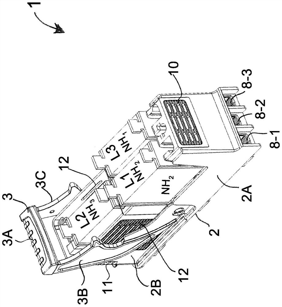
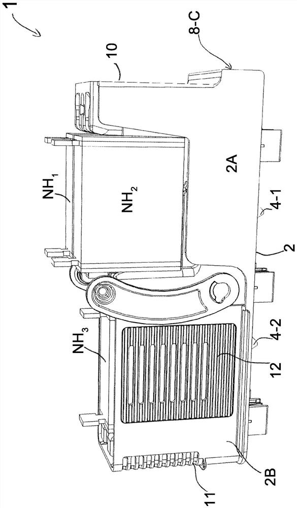
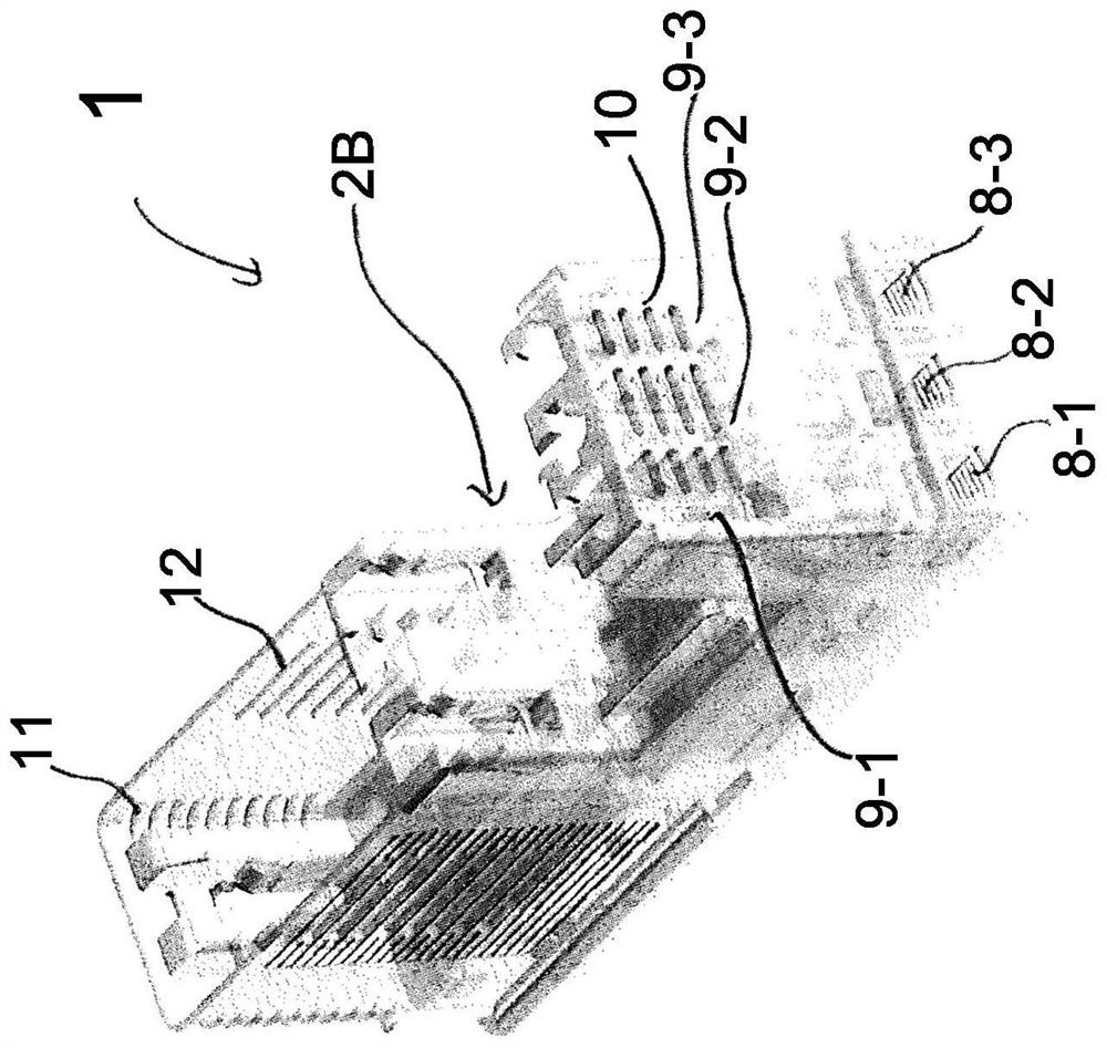
[0039]figure 1 An embodiment of the NH fuse load circuit switch 1 according to the present invention is shown in accordance with the present invention. The NH fuse load circuit switch or load circuit switch 1 is provided for a plurality of NH fuses. The load circuit switch 1 has a housing 2. The housing 2 is preferably composed of two portions and includes lower portions 2a and contact brackets 2b. In a preferred embodiment, the contact bracket 2b comprises a thermally conductive plastic. The housing 2 of the load circuit switch 1 is used to accommodate a plurality of NH fuses. To this end, it is preferred to setimage 3 The illustrated contact bracket 2b is shown. In the illustrated embodiment, the housing 2 of the load circuit switch 1 comprises three NH fuses NH1, NH2, NH3 for three different current phase L1, L2, L3. The NH fuse load circuit switch 1 can be assembled to the carrier rail, in particular on the bus bar. In the assembly state, the housing 2 of the load circuit switch...


PUM


Abstract

An NH fuse load break switch (1) has a housing (2) for accommodating a plurality of NH fuses, the NH fuses are vertically arranged in an assembled state, wherein the ) The waste heat generated by the NH fuse in the housing (2) is dissipated from the housing (2) upwards to the environment through the NH fuse arranged above it through the convection in the housing (2).

Description

Technical field[0001]The present invention relates to a NH fuse load circuit switch for a NH fuse having a high power density.Background technique[0002]The load circuit switch is used to disconnect the load or the appliance or device to the current or voltage distribution system. The current distribution system can include one or more power rails, especially bus bars. The electrical or load is used to connect to the current distribution system via the load circuit switch. The load circuit switch can include a plugable fuse, in particular NH fuse. In order to disconnect the current phase and the load, the user or operator can manually manipulate the joystick to disconnect the switch contacts within the negative carriage switch.[0003]A large amount of heat or exothermic is produced by the NH fuse in the housing of the NH fuse load circuit switch. Therefore, conventional load circuit switches have a relatively large housing, and correspondingly, in their assembly, there is a need for a...

Claims


Application Information

Patent Timeline
Patent Type & Authority Patents(China)
IPC IPC(8): H01H85/055H01H85/143H01H85/22H01H85/47
CPCH01H85/055H01H85/143H01H85/22H01H85/47H01H2085/0555H01H9/52H01H31/122
Inventor 菲利普·施泰因贝格尔胡贝特·伦克尔约拉姆·马塞尔克里斯托弗·库尔特
Owner 维纳尔电气系统有限公司
Why Eureka
Try Eureka