Light-emitting diode device and light-emitting device

A technology of light-emitting diodes and light-emitting devices, which is applied to electric solid devices, semiconductor devices, electrical components, etc., can solve the problems such as the development limit of external quantum efficiency of phosphors, poor stability of white LED devices, and the stability to be solved, so as to prevent water pollution. The effect of entering the fluorescent glue layer, strong light effect and stability, reducing the probability of moisture

Active Publication Date: 2019-09-24
XUYU OPTOELECTRONICSSHENZHEN CO LTD
View PDF14 Cites 4 Cited by
  • Summary
  • Abstract
  • Description
  • Claims
  • Application Information

AI Technical Summary

Problems solved by technology

Existing light-emitting diodes, such as white LED devices, are mainly realized by exciting phosphors with blue or violet chips, and the phosphors used in the lighting field mostly use aluminate green powder and nitride red powder with broadband emission, and the external quantum of the phosphors Efficiency development is gradually limited
At present, the industry usually uses large-size chips for low power to improve the light efficiency of white LED devices, but the manufacturing cost is too high
In recent years, Mn 4+ Doped K 2 SiF 6 The structure of fluoride red powder has attracted extensive attention in the industry due to its high light efficiency and narrow-band emission. Using this structure phosphor to replace nitride red powder can greatly improve the light efficiency of white LED devices, but the poor moisture resistance of the phosphor powder leads to the stability of white LED devices. Therefore, the current stability of white LED device lighting still needs to be solved

Method used


Image

  • Light-emitting diode device and light-emitting device
  • Light-emitting diode device and light-emitting device
  • Light-emitting diode device and light-emitting device

Examples


Embodiment 1

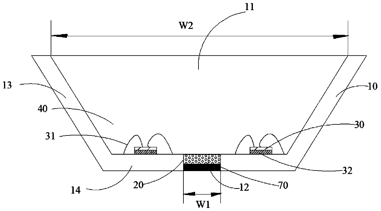
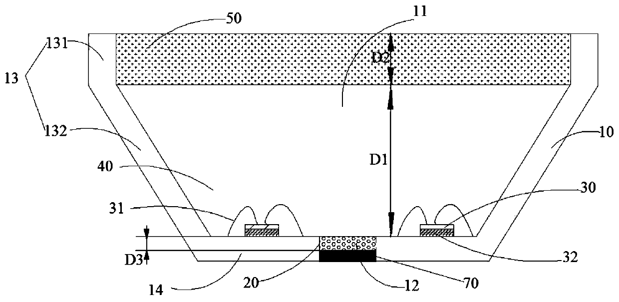
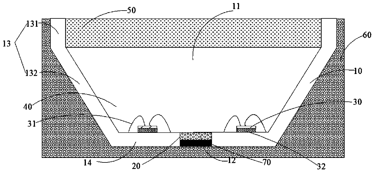
[0086] The structure of light-emitting diode devices such as figure 2 As shown, it includes a bracket 10 provided with a groove 11, a waterproof layer 20, a water-absorbing layer 70, a fluorescent glue layer 40, an anti-vulcanization layer 50 and two blue LED chips 30 arranged at intervals, and the bracket 10 includes a bottom wall 14 and side walls 13. The side wall 13 has a vertical section 131 and an inclined section 132, the angle between the vertical section 131 and the inclined section 132 is 120°, the thickness D2 of the anti-vulcanization layer 50 is the same as the height of the vertical section 131, and the fluorescent glue layer 40 The thickness D1 is the same as the height of the inclined section 132, the bottom wall is provided with a through hole 12, and the through hole 12 is provided with a waterproof layer formed by methyl silicone resin, wherein the width of the waterproof layer (that is, the width of the through hole) is the same as that of the fluorescent l...

Embodiment 2

[0088] The structure of the light-emitting diode device is the same as that of Embodiment 1, except that the weight ratio of the nitride red phosphor powder and the fluoride red phosphor powder is 1:3.

Embodiment 3

[0090] The structure of the light-emitting diode device is the same as that of Example 1, except that the weight ratio of the nitride red phosphor powder and the fluoride red phosphor powder is 1:4, and its light-color performance is shown in Table 1.


PUM


Abstract

The invention provides a light-emitting diode device and a light-emitting device, and relates to the technical field of light-emitting diodes. The light-emitting diode device comprises a support provided with a groove, wherein the support is provided with a through hole; a waterproof layer which is arranged in the through hole; at least one LED chip, wherein at least one LED chip is fixed on the support; a fluorescent glue layer which is disposed in the groove and covers at least one LED chip and the waterproof layer; a water absorption layer which is arranged in the through hole, wherein the water absorption layer is arranged on the surface, away from the fluorescent glue layer, of the waterproof layer. The light-emitting diode device has excellent waterproof performances, can protect the fluorescent glue layer from being affected with damp in the long-term use process, and further can greatly improve the lighting effect and stability of the light-emitting diode device.

Description

technical field [0001] The present invention relates to the technical field of light emitting diodes, in particular to a light emitting diode device and a light emitting device. Background technique [0002] Light Emitting Diode (LED) has the advantages of high efficiency, energy saving, environmental protection, long life, small size, and easy maintenance, and has attracted extensive attention from researchers at home and abroad. Existing light-emitting diodes, such as white LED devices, are mainly realized by exciting phosphors with blue or purple chips, and the phosphors used in the lighting field mostly use aluminate green powder and nitride red powder with broadband emission, and the external quantum of the phosphors Efficiency development is gradually limited. At present, the industry usually uses large-size chips for low power to improve the light efficiency of white LED devices, but the preparation cost is too high. In recent years, Mn 4+ Doped K 2 SiF 6 The str...

Claims


Application Information

Patent Timeline
Patent Type & Authority Applications(China)
IPC IPC(8): H01L33/48H01L33/50H01L25/075
CPCH01L25/0753H01L33/486H01L33/50H01L2933/0033H01L2933/0041
Inventor 陈磊蔡济隆林金填周少翔
Owner XUYU OPTOELECTRONICSSHENZHEN CO LTD
Why Eureka
Try Eureka