
Self-adaptive transient response optimization circuit suitable for peak current mode DC-DC converter

A DC-DC, peak current technology, applied in the direction of converting DC power input to DC power output, adjusting electrical variables, instruments, etc., can solve problems such as slow transient response, achieve system stability, low noise, and improve transient response speed effect

Active Publication Date: 2019-09-24
UNIV OF ELECTRONICS SCI & TECH OF CHINA
View PDF8 Cites 12 Cited by
  • Summary
  • Abstract
  • Description
  • Claims
  • Application Information

AI Technical Summary

Problems solved by technology

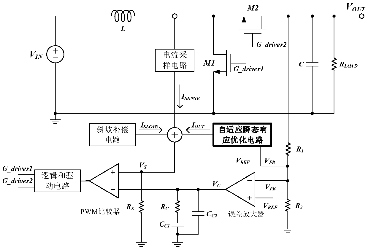
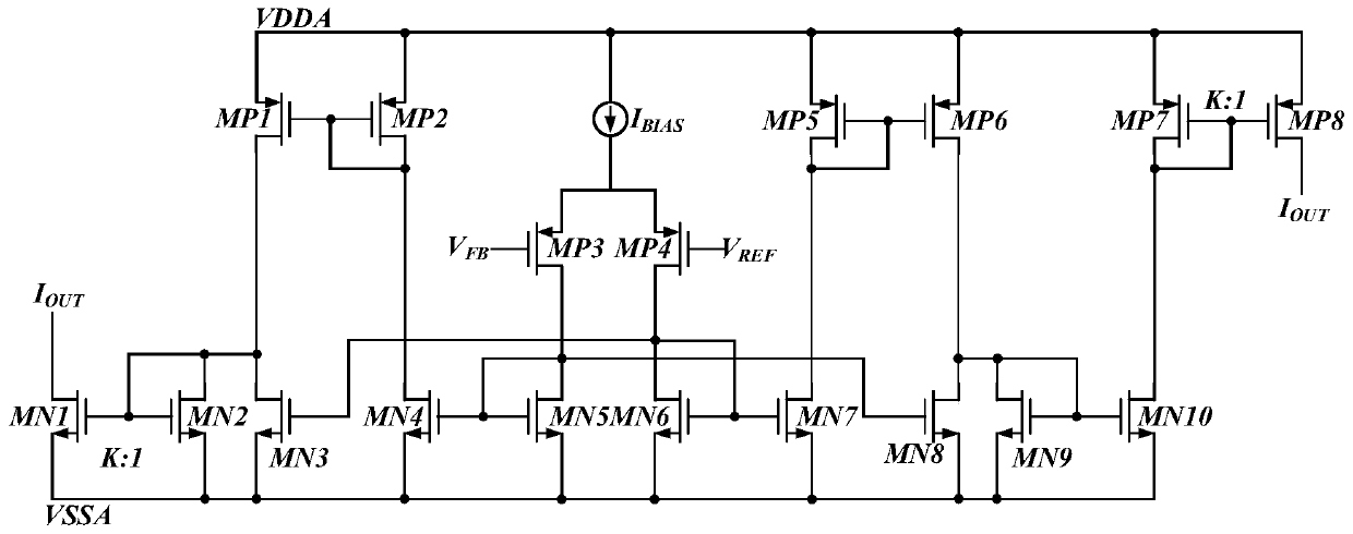
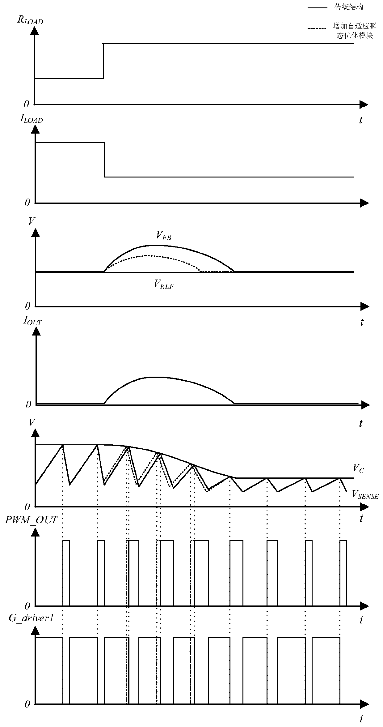
[0004] Aiming at the problem of slow transient response of the DC-DC converter system caused by different loads or input and output in the traditional specific load point optimization method, the present invention proposes an adaptive transient response method suitable for peak current mode DC-DC converters. State response optimization circuit, according to the feedback voltage V of the DC-DC converter FB and reference voltage V REF The change adaptively changes the size and direction of the generated current, and is connected with the inductor current sampling signal I SENSE and slope compensated output signal I SLOPE superimposed and converted into a voltage signal V through the resistance S Then it is input to the positive input terminal of the PWM comparator, which speeds up the adjustment speed of the original DC-DC converter system loop during the load step from the perspective of large signals, and optimizes the transient response of the system

Method used


Image

  • Self-adaptive transient response optimization circuit suitable for peak current mode DC-DC converter
  • Self-adaptive transient response optimization circuit suitable for peak current mode DC-DC converter
  • Self-adaptive transient response optimization circuit suitable for peak current mode DC-DC converter

Examples


Embodiment Construction

[0022] The technical solution of the present invention will be described in detail below in conjunction with the accompanying drawings and specific embodiments.

[0023] Such as figure 1 Shown is the application schematic diagram of the adaptive transient response optimization circuit suitable for the peak current mode DC-DC converter proposed by the present invention. The adaptive transient response optimization circuit has two input terminals and one output terminal. The adaptive transient response optimization circuit has two input terminals and one output terminal. The first input terminal of the state response optimization circuit is connected to the feedback voltage V FB , the second input terminal is connected to the reference voltage V REF , adaptive transient response optimization circuit output current signal I OUT , current signal I OUT Be the transient enhanced current signal that the present invention produces, the transient enhanced current signal I of generat...


PUM


Abstract

The invention discloses a self-adaptive transient response optimization circuit suitable for a peak current mode DC-DC converter, and belongs to the technical field of electronic circuits. The circuit adaptively adjusts and controls the magnitude and direction of an output transient enhanced current signal according to the actual conditions of a feedback voltage and a reference voltage of the DC converter, enables a generated current signal to be superposed with an inductive current sampling signal and a slope compensation signal, and converts the signal into a voltage signal through a resistor, and then inputs the voltage signal to the positive input end of a PWM comparator, so that the adjustment speed of an original system loop in a load step is increased from the perspective of a large signal, and the transient response of the system is optimized. Compared with a traditional transient response optimization circuit, the circuit can adaptively provide the transient enhanced current signal related to the output voltage change, has the characteristics of low noise and higher system stability, and can improve the transient response speed of the system effectively.

Description

technical field [0001] The invention belongs to the technical field of electronic circuits and relates to an adaptive transient response optimization circuit suitable for peak current mode DC-DC converters. Background technique [0002] Currently, there are increasing demands on load current and fast output transient response in many aspects of DC-DC converter applications. In order to address the fast switching of loads under different application conditions, it is necessary to enable the output of the power supply to have a fast load response capability to meet this requirement. [0003] The traditional method of transient response optimization is generally to optimize the system loop at the small signal level to optimize the loop characteristics under different load conditions. However, traditional methods often only optimize at specific load points, and in actual use, DC-DC converters usually have many different load conditions, including different input and output volt...

Claims


Application Information

Patent Timeline
IPC IPC(8): H02M3/158
CPCH02M3/158
Inventor 罗萍王晨阳周先立彭定明李博王浩
Owner UNIV OF ELECTRONICS SCI & TECH OF CHINA
Learn More