

Short bar machining line
An assembly line and short rod technology, applied in the field of assembly line, can solve problems such as low production efficiency, inability to realize industrialization, and short rods that cannot be processed on the assembly line
- Summary
- Abstract
- Description
- Claims
- Application Information
AI Technical Summary
Problems solved by technology
Method used
Image

Examples
Embodiment 1
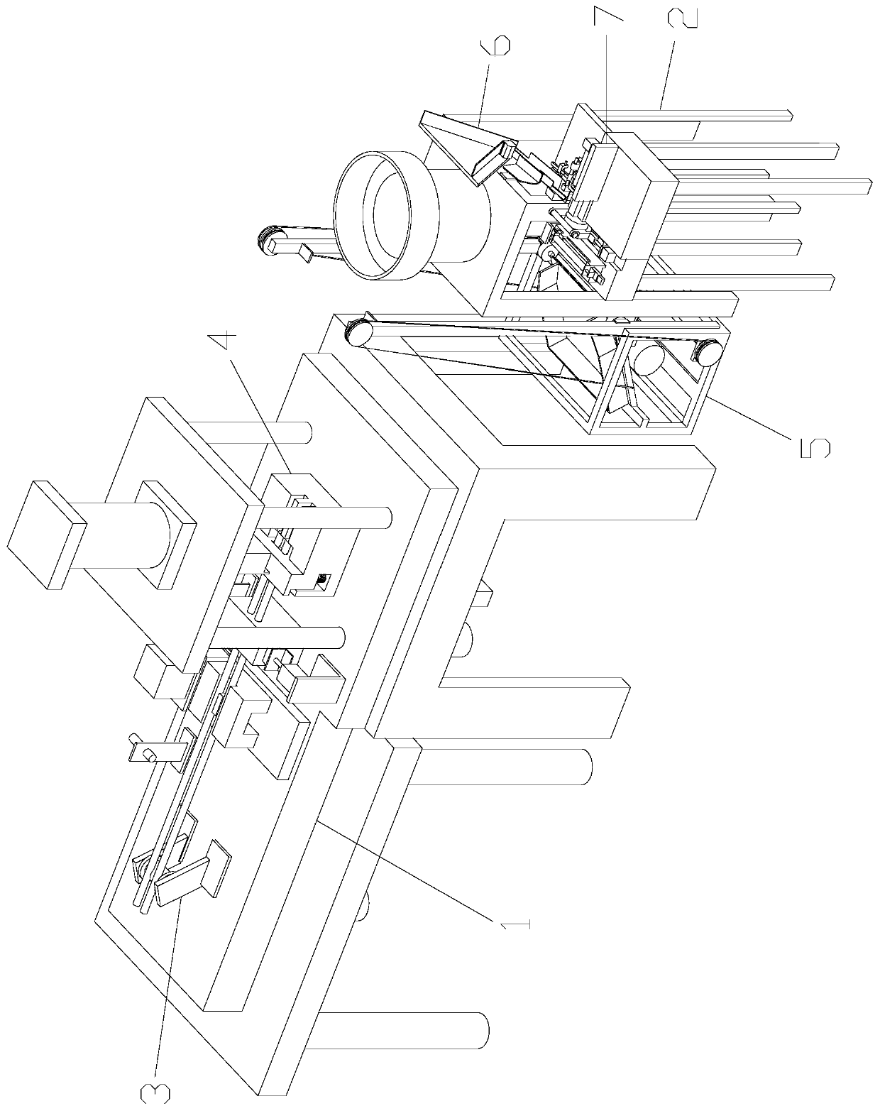
[0049] Embodiment 1: This short rod processing line includes a short rod cutting device 1 and a short rod grinding device 2. The short rod cutting device 1 includes a long rod pushing unit 3 and is used in conjunction with the long rod pushing unit 3 and is used for processing long rods. Cutting and blanking unit 4 for section processing of rods, short rod grinding device 2 includes short rod lifting and feeding unit 5, bucket-shaped feeding unit 6 used in conjunction with short rod lifting and feeding unit 5, and automatic clamping with grinding function Feeding unit 7. In this way, this assembly line is used to process long rods into short rods in sections, and after cutting, the outer surface of the short rods is ground to realize integrated process processing. First, the long rods are sent to the Enter into the cutting and blanking unit 4, and then complete the cutting of the short rods. The cut short rods fall into the short rod lifting unit 5, and are sent to the bucket-...
Embodiment 2
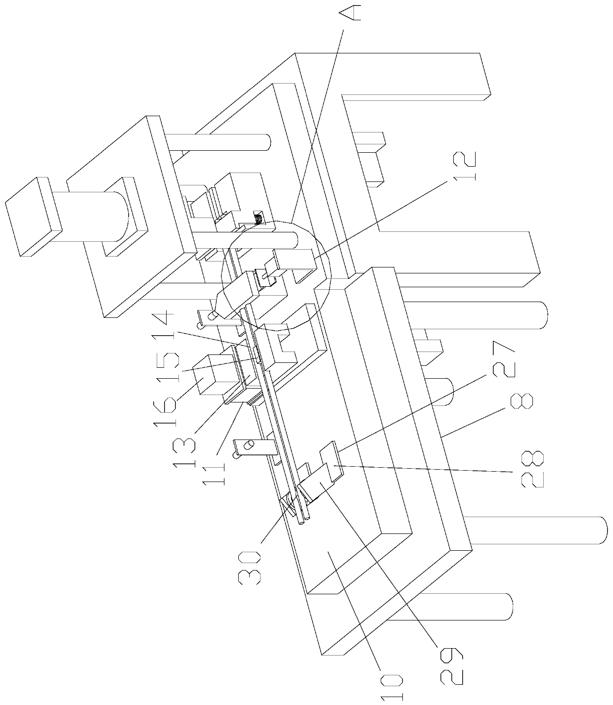
[0050] Embodiment 2: The long rod pushing unit 3 includes a first frame body 8, and the first frame body 8 is provided with a carriage 10 slidably connected to the first carriage body 8, a driving part 11 installed on the carriage 10, and an installation The limit part 12 on the first frame body 8 and placed on the side of the driving part 11; the driving part 11 includes a mounting block 13 installed on the carriage 10, and the upper end of the mounting block 13 is provided with a through slot for the long rod to pass through 14. The middle part of the through groove 14 is provided with a telescopic block 15 that is consistent with the opening direction of the through groove 14 and expands and contracts in the installation block 13. The telescopic block 15 realizes up and down expansion and contraction through the first cylinder 16; the first cylinder 16 is placed in the installation block 13 At the front end, the bottom of the first cylinder 16 is provided with a first base 1...
Embodiment 3
[0053] Embodiment 3: Cutting and blanking unit 4 includes a second frame body 31, which is provided with a cutting portion 33 and a die housing 34 placed at the lower end of the cutting portion 33 and used in conjunction with the cutting portion 33, the die The housing 34 includes an upper housing 35, a lower housing 36, and a push rod 37 placed between the upper housing 35 and the lower housing 36. The lower housing 36 is provided with a passage 38 for the upper housing 35 to exist in. , the lower housing 36 and the upper housing 35 are connected by the second spring 39, the upper housing 35 has a storage groove 40, the push rod 37 is placed in the middle of the channel 38 and placed in the storage groove 40, the push rod 37 The right end face and the right end face of the channel 38 are in a face-to-face fit, and there is a feed channel 41 between the left end face of the ejector rod 37 and the left end face of the channel 38, and the top of the ejector rod 37 has a semi-arc ...
PUM
 Abstract
Description
Claims
Application Information