Heating plate mounting and moving mechanism

A technology of moving mechanism and heating plate, which is applied in the field of hot plate welding machine, can solve the problems that affect the processing accuracy and service life of the heating plate, and the installation and fixed structure of the heating plate cannot meet the requirements of automatic disassembly and replacement at the same time, so as to achieve the effect of improving efficiency

Pending Publication Date: 2019-09-27
SUZHOU KEBER PRECISION MACHINERY
View PDF0 Cites 0 Cited by
  • Summary
  • Abstract
  • Description
  • Claims
  • Application Information

AI Technical Summary

Problems solved by technology

[0002] The hot plate welding machine is used for welding various accessories. The hot plate welding machine uses the principle of electric heating to weld with the mechanical transmission structure, which can make up for the shortcomings of the ultrasonic welding machine in welding large and special plastic workpieces. The hot plate welding machine is more It is suitable for welding thermoplastic materials such as PP and PE, as well as plastic workpieces with large and complex welding joints; while the existing hot plate welding machine, the installation and fixing structure of the heating plate cannot meet the needs of automatic replacement and overcoming thermal expansion at the same time. It will affect the processing accuracy and service life of the heating plate

Method used


Image

  • Heating plate mounting and moving mechanism
  • Heating plate mounting and moving mechanism

Examples


Embodiment Construction

[0013] The present invention will be further described in detail below in conjunction with the accompanying drawings and specific embodiments.

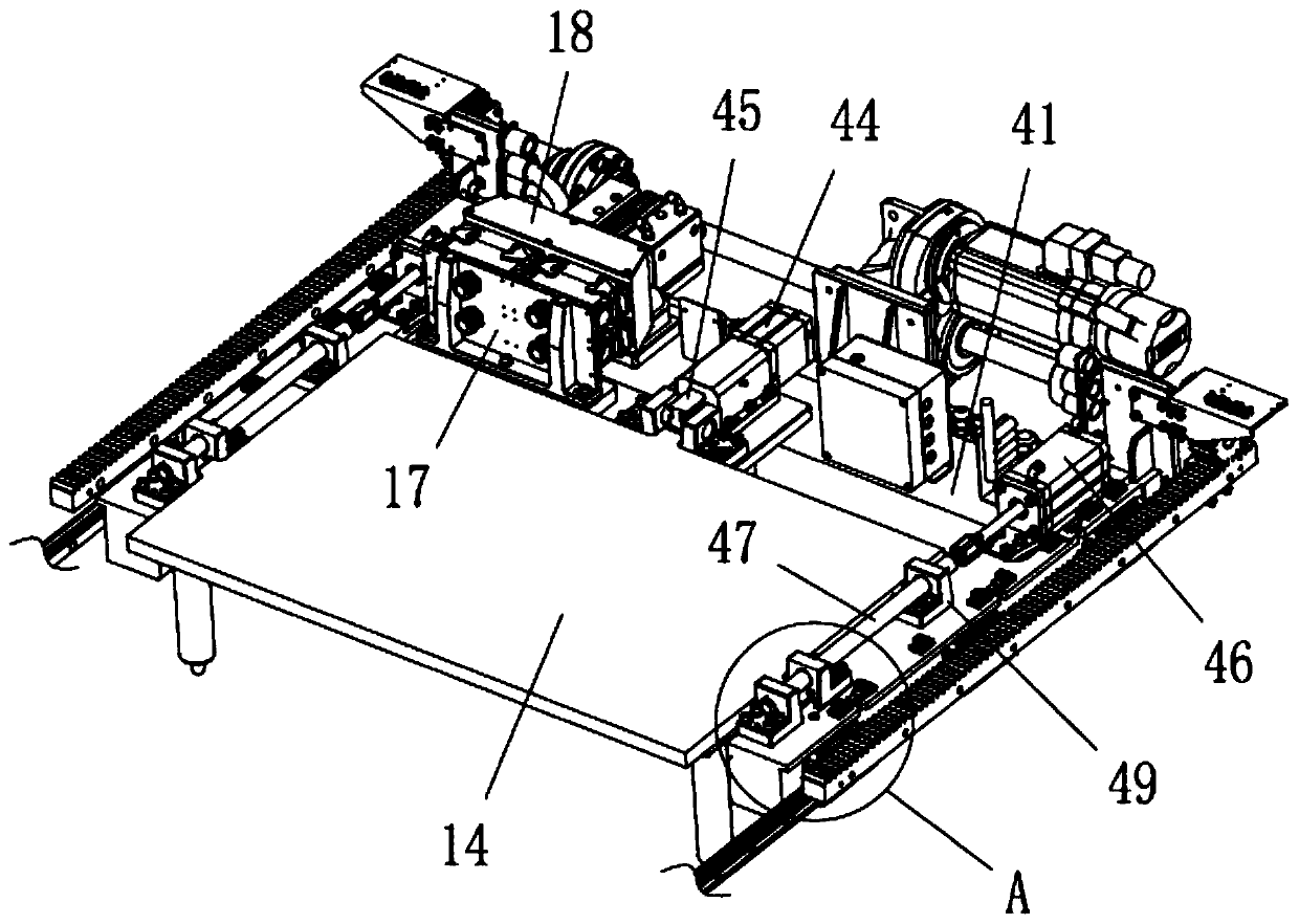
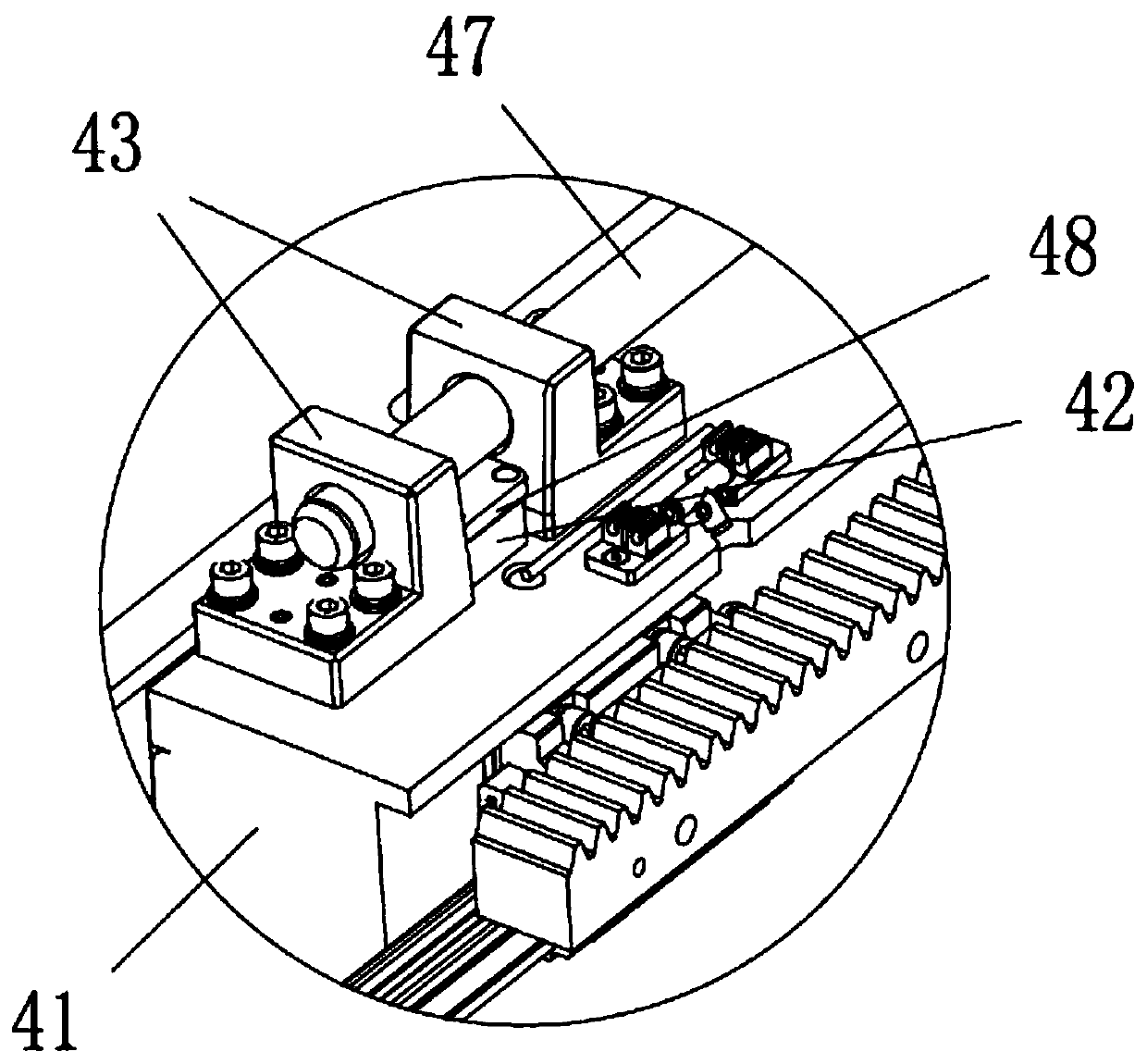
[0014] Such as Figure 1-2 As shown, the heating plate installation and moving mechanism of the present invention includes a hot plate moving frame 41, a heating plate and a forward drive assembly, the forward drive assembly drives the hot plate mobile frame 41 to move back and forth, and the forward drive assembly includes a servo motor, Reduction box, transmission shaft and rack, tooth rack is arranged on the left and right sides of hot plate mobile frame 41, and servo motor drives transmission shaft to rotate through reduction box, and the two ends of transmission shaft all pass gear and hot plate mobile frame 41 left and right sides rack fit.

[0015] The rear side and the left and right sides of the heating plate 14 all have an outwardly protruding ear portion 42, and the hot plate moving frame 41 is provided with 3 sets of hot ...


PUM


Abstract

The invention discloses a heating plate mounting and moving mechanism. The heating plate mounting and moving mechanism comprises a hot plate moving frame, a heating plate and a forward-moving driving assembly, wherein an ear part is arranged on the heating plate, a hot plate positioning seat, a hot plate rear lock assembly and a side edge locking assembly are arranged on the hot plate moving frame, and the hot plate positioning seat, the hot plate rear lock assembly and the side edge locking assembly are matched with the ear part of the heating plate; the hot plate rear lock assembly comprises a rear lock cylinder and a rear lock push block, and the side edge locking assembly comprises a side air cylinder and a side pressure rod; a heating socket is further arranged on the heating plate, and a heating plug is further arranged on the hot plate moving frame. According to the heating plate mounting and moving mechanism, the heating plate positioning seat, the heat plate rear lock assembly and the side edge locking assembly are used for matching and locking the ear part of the heating plate; when the heating plate works to enable the ear part to be expanded with heat, the ear part can generate slight deformation toward the outer side, the machining precision of the hot plate and the hot plate rear lock assembly and the side edge locking assembly cannot be influenced, the heating plate can be unlocked without waiting for cooling of the heating plate, the heating plate can be removed and replaced, and the efficiency is improved.

Description

technical field [0001] The invention relates to the technical field of hot plate welding machines, in particular to a heating plate installation and moving mechanism for hot plate welding machines. Background technique [0002] The hot plate welding machine is used for welding various accessories. The hot plate welding machine uses the principle of electric heating to weld with the mechanical transmission structure, which can make up for the shortcomings of the ultrasonic welding machine in welding large and special plastic workpieces. The hot plate welding machine is more It is suitable for welding thermoplastic materials such as PP and PE, as well as plastic workpieces with large and complex welding joints; while the existing hot plate welding machine, the installation and fixing structure of the heating plate cannot meet the needs of automatic replacement and overcoming thermal expansion at the same time. It will affect the processing accuracy and service life of the heat...

Claims


Application Information

Patent Timeline
IPC IPC(8): B29C65/18
CPCB29C65/18
Inventor 文华波毕林龙
Owner SUZHOU KEBER PRECISION MACHINERY
Why Eureka
Try Eureka