Head lamp protection device and car
A protection device and headlight technology, applied in the field of auto parts, can solve the problems of expensive headlights, low impact force, damaged headlights, etc., and achieve the effects of easy displacement, reduction of contact area, and reduction of maintenance costs.
- Summary
- Abstract
- Description
- Claims
- Application Information
AI Technical Summary
Problems solved by technology
Method used
Image
Examples
Embodiment 1
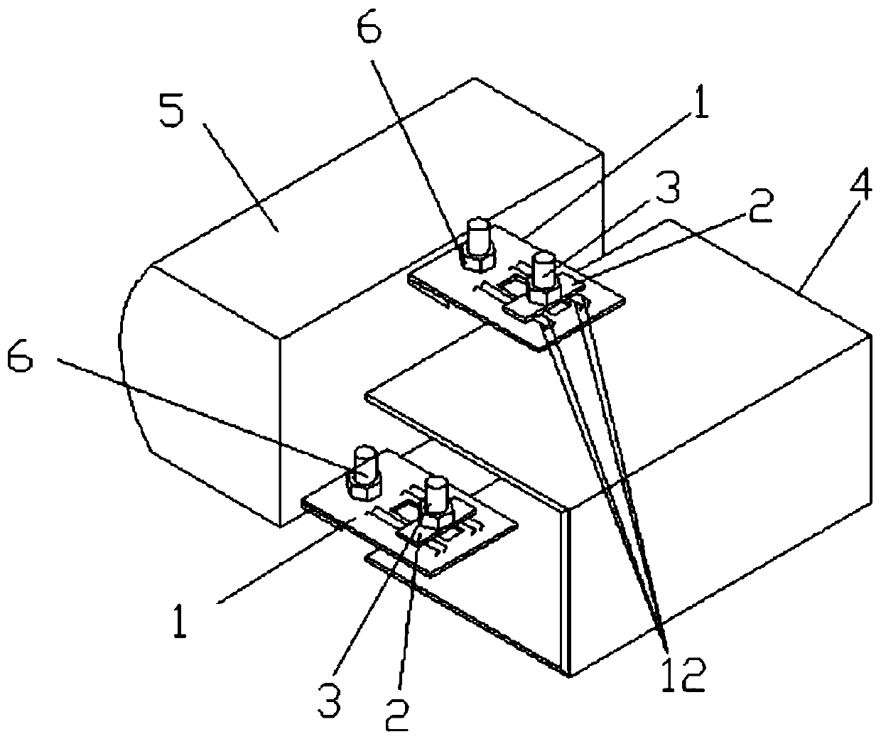
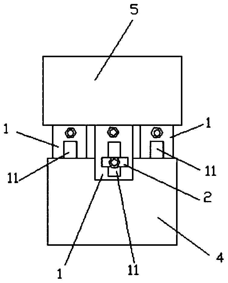
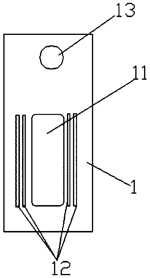
[0030] like Figures 1 to 4 As shown, Embodiment 1 of the present invention provides a headlight protection device. The headlight protection device includes a sliding connection part 1 , a pressing part 2 and a fastener 3 . There are prefabricated holes (not shown) on the headlight 5, and one end of the sliding connection part 1 is provided with a mounting hole 13. During installation, the connecting bolt 6 is passed through the prefabricated hole and the installation hole 13, and after tightening, the sliding connection part 1 is connected to the installation hole 13. The headlights 5 are fixedly connected, so that the two become a rigid whole, and the bolt connection is adopted here to facilitate the replacement of the sliding connecting part 1 after the headlights are impacted. In another embodiment of the present invention, a welding connection method is adopted here, which can avoid loosening of the connection between the headlight 5 and the sliding connection portion 1 ...
Embodiment 2
[0036] The difference between this embodiment and Embodiment 1 mainly lies in the shape of the connection port 11 and the distribution of the raised bars 12 . In this embodiment, as Image 6 As shown, the shape of the connection port 11 is a right-angled triangle, and the three inner corners of the right-angled triangle are all rounded, so as to eliminate the concentrated stress near each inner corner and prolong the service life of the sliding connection part 1; the fastener 3 passes through the connection port 11. The side of the smaller acute angle is connected to the pressing part 2 and the body 4 , the longer right-angled side of the connection port 11 is parallel to the vehicle's straight-forward direction, and the other right-angled side is perpendicular to the vehicle's straight-forward direction. In order to have enough space for the sliding connection part 1 to be displaced relative to the body body 4 when the headlight 5 is hit by a frontal or side-forward impact, t...
Embodiment 3
[0040] The difference between this embodiment and Embodiment 1 mainly lies in the shape of the connection port 11 and the distribution of the raised bars 12 . In this embodiment, as Figure 8 As shown, the shape of the connection port 11 is an isosceles trapezoid, and the smaller acute angle of the isosceles trapezoid is 30°˜70°. In a preferred embodiment of the present invention, the smaller acute angle of the isosceles trapezoid is 60°. The four inner corners of the isosceles trapezoid are all rounded to eliminate the concentrated stress near each inner corner and prolong the service life of the sliding connection part 1; the two parallel sides of the connection port 11 are perpendicular to the direction of the car going straight, among which the longer The parallel side is arranged on the side close to the mounting hole 13 . The fastener 3 is connected to the pressing part 2 and the body body 4 through the side of the smaller parallel side of the connecting port 1, so that...
PUM
| Property | Measurement | Unit |
|---|---|---|
| Acute angle | aaaaa | aaaaa |
| Length | aaaaa | aaaaa |
| Width | aaaaa | aaaaa |
Abstract
Description
Claims
Application Information
 - R&D Engineer
- R&D Manager
- IP Professional
- Industry Leading Data Capabilities
- Powerful AI technology
- Patent DNA Extraction
Browse by: Latest US Patents, China's latest patents, Technical Efficacy Thesaurus, Application Domain, Technology Topic, Popular Technical Reports.
© 2024 PatSnap. All rights reserved.Legal|Privacy policy|Modern Slavery Act Transparency Statement|Sitemap|About US| Contact US: help@patsnap.com


