
Downhole setting tools and methods

A tool and height-oriented technology, applied in earth-moving drilling, sealing/packaging, wellbore/well components, etc., can solve the problems of great influence of workers' technical level, unstable propellant thrust, and high cost of propellant. Overcome the effects of high material control and operator requirements, stable and continuous explosive force, and low construction and operation costs

Active Publication Date: 2020-10-16
CHINA UNIV OF PETROLEUM (BEIJING)
View PDF6 Cites 0 Cited by
  • Summary
  • Abstract
  • Description
  • Claims
  • Application Information

AI Technical Summary

Problems solved by technology

[0006] 1. Because the gunpowder column is a non-standard part and needs to be customized, the thrust generated by the combustion of the gunpowder column is not stable enough and is greatly affected by the technical level of the workers;
[0007] 2. Gunpowder is a controlled item, the transportation approval process is complicated, and the custom processing cycle is long, it is not easy to produce and store in batches, and it is not convenient for flexible construction on site;
[0008] 3. The cost of gunpowder column is relatively high
[0011] 1. The overall length of downhole tools is long, which is not conducive to wells with large turning points;
[0012] 2. The internal structure is complex and the number of parts is large, limited by the technical level of workers, and the speed and quality of tool installation are limited;
[0013] 3. The post-maintenance of the complex hydraulic structure is extremely complicated
These deficiencies limit the applicability and economy of oil and gas well plugging operations
[0014] To sum up, neither hydraulic setting nor gunpowder explosion setting can better meet the needs of setting operation of spacers and bridge plugs in staged fracturing production.

Method used


Image

  • Downhole setting tools and methods
  • Downhole setting tools and methods
  • Downhole setting tools and methods

Examples


Embodiment Construction

[0038] The details of the present invention can be understood more clearly with reference to the accompanying drawings and the description of specific embodiments of the present invention. However, the specific embodiments of the present invention described here are only for the purpose of explaining the present invention, and should not be construed as limiting the present invention in any way. Under the teaching of the present invention, any possible modification based on the present invention can be conceived by a skilled person, and these should be regarded as belonging to the scope of the present invention. It should be noted that when an element is referred to as being “disposed on” another element, it may be directly on the other element or there may also be an intervening element. When an element is referred to as being "connected to" another element, it can be directly connected to the other element or intervening elements may also be present. The terms "mounted", "c...


PUM


Abstract

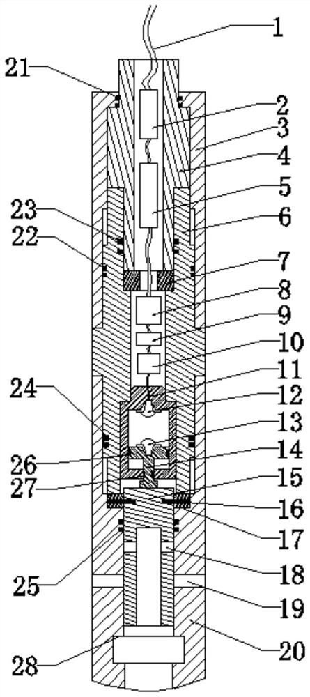
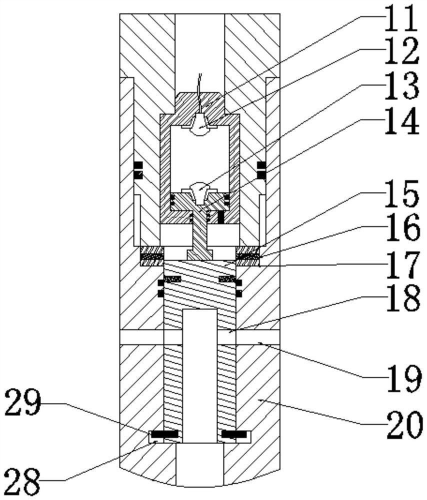
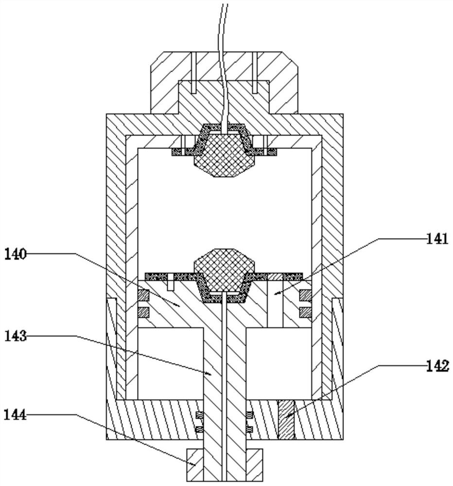
The invention discloses a downhole setting tool and a method. The tool comprises a shell connecting mechanism provided with cavity flow channels, an impulse power output mechanism and an electro-hydraulic explosion starting mechanism. The electro-hydraulic explosion starting mechanism comprises a piston cavity, a first electrode, a second electrode, a piston rod and a liquid channel switch piston, wherein the first electrode and the second electrode are arranged in the position cavity, and metal powder suspended electrical explosion liquid is accommodated in the space, between the first electrode and the second electrode, in the piston cavity; the liquid channel switch piston abuts against the lower portion of the piston rod and is fixed to the shell connecting mechanism through shear pins; and position flow channels are formed in the liquid channel switch piston. After the electro-hydraulic explosion starting mechanism is started, the piston rod can be pushed downwards, the shear pins are sheared off, and the piston flow channels communicate with the cavity flow channels. By means of the downhole setting tool and the method, the demand for setting work of packers and bridge plugs in staged fracturing exploitation can be better met.

Description

technical field [0001] The invention relates to the technical field of petroleum downhole tools, in particular to a downhole setting tool and method. Background technique [0002] The statements in this section only provide background information related to the present disclosure and may not constitute prior art. [0003] Low-permeability tight oil and gas reservoirs have become the main body of oil and gas production. For this kind of oil and gas reservoirs, staged fracturing is widely used in the production process. Among them, when the staged fracturing technology is used, bridge plugs and plugging devices are commonly used as plugging parts, and the downhole string is separated by the two to realize plugging in the casing. [0004] At present, there are two main types of setting methods for packers and bridge plugs, namely hydraulic setting and explosive setting. Among them, the hydraulic setting is to control the liquid pressure on the ground through the complex liqu...

Claims


Application Information

Patent Timeline
Patent Type & Authority Patents(China)
IPC IPC(8): E21B33/134E21B33/12
CPCE21B33/12E21B33/1208E21B33/134
Inventor 郭岩宝韩忠星王德国谭海
Owner CHINA UNIV OF PETROLEUM (BEIJING)
Learn More