Vibration reduction device suitable for aero-engine reduction box

A technology for aero-engines and vibration damping devices, which is applied to transmission parts, mechanical equipment, belts/chains/gears, etc. It can solve the problems of gear box broken teeth and shafts, reduced vibration damping effect, and increased powertrain weight

Active Publication Date: 2019-09-27
安徽航瑞航空动力装备有限公司
View PDF6 Cites 7 Cited by
  • Summary
  • Abstract
  • Description
  • Claims
  • Application Information

AI Technical Summary

Problems solved by technology

The engine is directly connected to the gearbox, and the torsional vibration of the engine is completely transmitted to the gearbox through the output end. This torsional vibration produces a huge alternating impact load, which is transmitted to the gears, shafts and other parts in the gearbox. , will greatly reduce the reliability of the gearbox, which may cause the vibration and noise of the gearbox to be very loud, or lead to broken teeth and shafts of the gearbox, damage to the powertrain, and even the tragedy of crashing the plane.
[0003] Generally, hard connections cannot be used between the engine and the gearbox. Referring to the current vehicle structure, the engine is equipped with a single-mass flywheel, which is connected to the gearbox through a diaphragm spring clutch and a clutch pressure plate. With this structure, the powertrain A 10kg increase in weight will greatly reduce the power-to-weight ratio of the powertrain
[0004] Generally, the powertrain for aviation use, the connection between the engine and the gearbox is also made of rubber damping material, which is generally used in the powertrain below 30KW, and for the powertrain above 80KW, rubber sleeves are used to reduce vibration. Vibration will reduce the vibration damping effect, the weight will increase significantly, and the reliability will decrease

Method used


Image

  • Vibration reduction device suitable for aero-engine reduction box
  • Vibration reduction device suitable for aero-engine reduction box
  • Vibration reduction device suitable for aero-engine reduction box

Examples


Embodiment Construction

[0025] The specific embodiment of the present invention will be described in further detail by describing the embodiments below with reference to the accompanying drawings, the purpose is to help those skilled in the art to have a more complete, accurate and in-depth understanding of the concept and technical solutions of the present invention, and contribute to its implementation.

[0026] It should be noted that in the following embodiments, the "first" and "second" do not represent an absolute distinction in structure and / or function, nor do they represent a sequence of execution, but are only for Easy to describe.

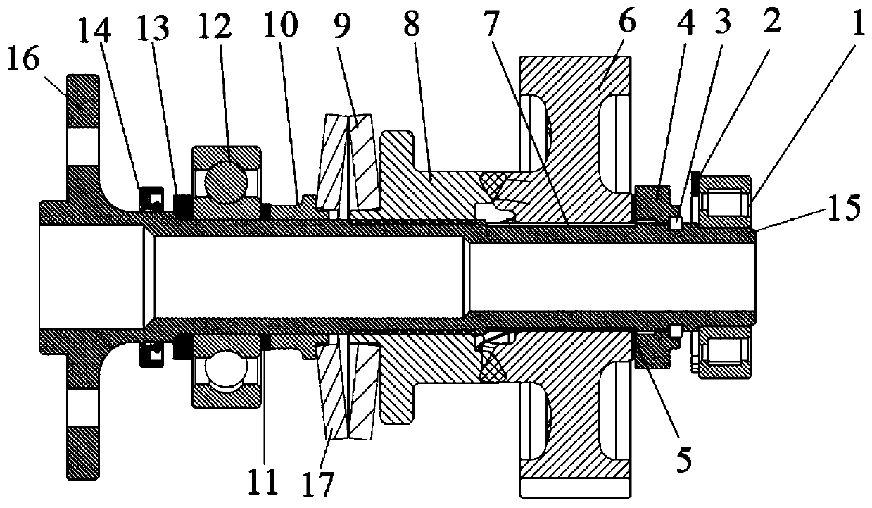
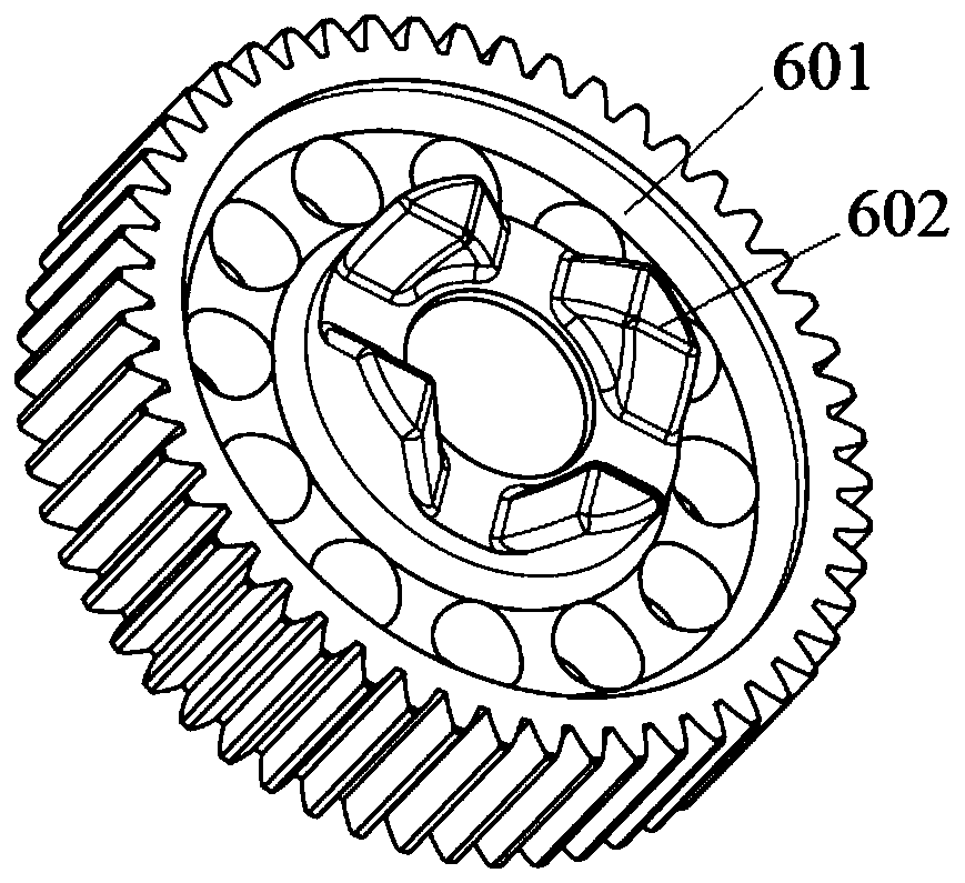
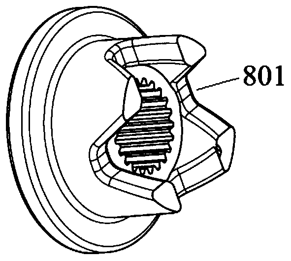
[0027] Such as Figure 1 to Figure 5 As shown, the present invention provides a vibration damping device suitable for an aero-engine gearbox, including an output shaft for connecting with the aero-engine, a power transmission mechanism for transferring torque from an aero-engine to the output shaft, and a sleeve The spring seat 10 on the output shaft and the ...


PUM


Abstract

The invention discloses a vibration reduction device suitable for an aero-engine reduction box. The vibration reduction device comprises an output shaft used for being connected with the reduction box, a power transmission mechanism used for transmitting the torque from an aero-engine to the output shaft, a spring seat arranged on the output shaft in a sleeving mode and a spring assembly which is arranged between the spring seat and the power transmission mechanism and used for applying an axial elastic acting force to the power transmission mechanism. According to the vibration reduction device suitable for the aero-engine reduction box, the spring assembly is arranged to absorb the torsional vibration energy of the engine, a buffering effect is achieved between the engine and the reduction box, then the vibration reduction effect is achieved, through shaft teeth in the reduction box, a gear is prevented from being damaged, and the reliability and comfort of an aero-power assembly are improved.

Description

technical field [0001] The invention belongs to the technical field of engine reduction box power, in particular, the invention relates to a vibration damping device suitable for an aircraft engine reduction box. Background technique [0002] At present, in the field of piston aeroengines, some engines with simple structures, directly driving propellers, and small power-to-weight ratios cannot meet the purposes of aircraft. Aircraft now require high power-heavy and low fuel consumption for the powertrain. If the engine direct-drive propeller is used, the power-to-weight ratio of the engine will be small. Therefore, the commonly used solution is to increase the power of the engine by high-speed and high-pressure. The speed required by the actual aircraft will be lower than the speed of a single engine, so in general, it is necessary to add a deceleration mechanism separately to reduce the output speed of the powertrain, so as to achieve a perfect match between the engine and ...

Claims


Application Information

Patent Timeline
Patent Type & Authority Applications(China)
IPC IPC(8): F16H57/021F16H57/028
CPCF16H57/021F16H57/028F16H2057/02039
Inventor 李为松李康杨国玺谢小祥
Owner 安徽航瑞航空动力装备有限公司
Why Eureka
Try Eureka