Rotatable electric slit

A slit and electric technology, applied in the field of optical slits, can solve the problems that optical slits cannot be slit direction and adjustment, and achieve the effect of simple structure, easy operation and precise adjustment

Active Publication Date: 2019-09-27
XI'AN INST OF OPTICS & FINE MECHANICS - CHINESE ACAD OF SCI
View PDF13 Cites 1 Cited by
  • Summary
  • Abstract
  • Description
  • Claims
  • Application Information

AI Technical Summary

Problems solved by technology

[0005] The purpose of the present invention is to provide a rotatable electric slit in order to solve the problem that the optical slit in the prior art can only adjust the slit width but not the slit direction.

Method used


Image

  • Rotatable electric slit
  • Rotatable electric slit
  • Rotatable electric slit

Examples


Embodiment 1

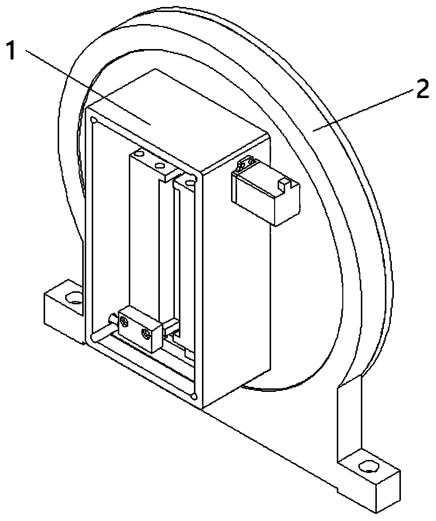
[0045] A rotatable electric slit in this embodiment, combined with figure 1 , figure 2 , image 3 as well as Figure 4 As shown, it includes an electric slit device 1 and a direction adjustment device 2;

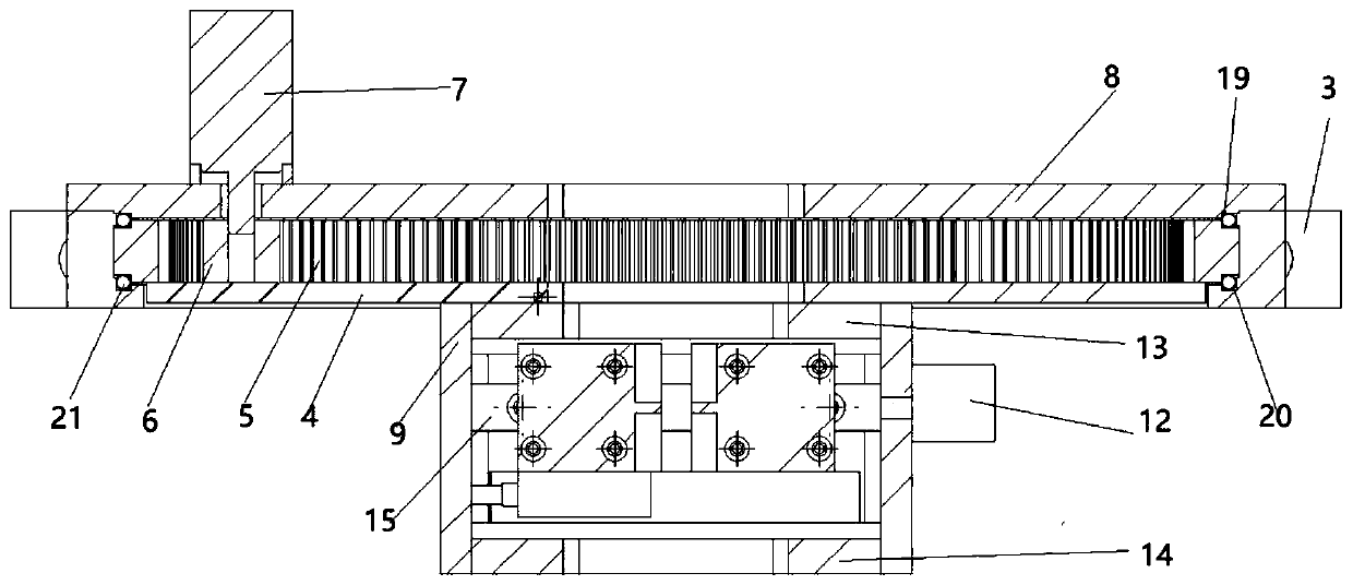
[0046] The direction adjusting device 2 includes an annular seat 3, a fixed plate 8, a rotating plate 4, an inner ring gear 5, a driving gear 6 and a first stepping motor 7;

[0047] The fixed plate 8 is fixedly installed on one end of the annular seat 3, and the rotating plate 4 is located at the other end of the annular seat 3, so that a circular cavity is formed between the annular seat 3, the fixed plate 8 and the rotating plate 4; the ring gear 5 and the annular The seat 3 is coaxial and located in the circular cavity, and a bearing assembly is arranged between the outer surface of the ring gear 5 and the inner surface of the ring seat 3; one end face of the rotating plate 4 is fixedly connected with the ring gear 5, and the other end face An electric slit device 1...

Embodiment 2

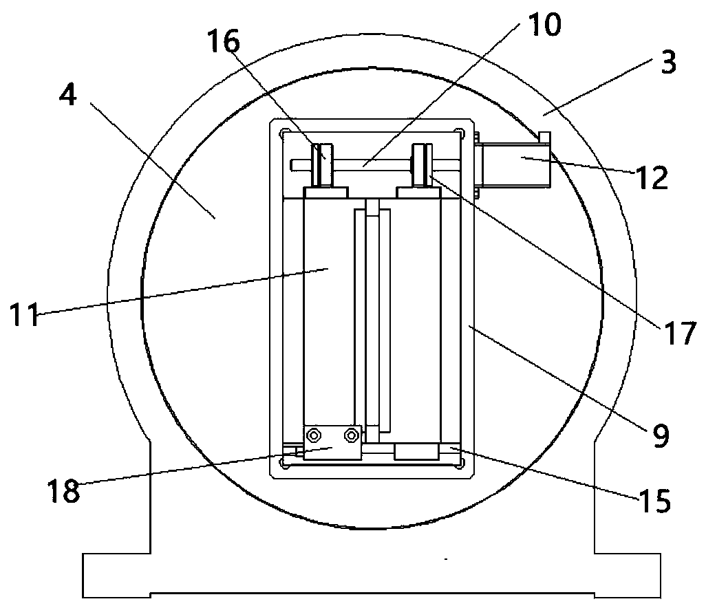
[0059] combine figure 1 , figure 2 , image 3 as well as Figure 4 As shown, the structure of the rotatable electric slit in this embodiment is basically the same as that in Embodiment 1, and the main difference is that the electric slit device includes a housing 9, a double screw screw 10, two slit doors 11 and a second slit. Two stepper motors 12;

[0060] The housing 9 includes a hollow frame formed by connecting four rectangular plates end to end, and a front end cover 13 and a rear end cover 14 arranged on the hollow frame; Adapted through holes; guide rails 15 are installed on the bottom inner wall of the hollow frame, and a double-rotation screw 10 is installed on the top of the hollow frame. Nuts 16 are installed on the right-handed and right-handed thread sections; one end of the two slit doors 11 is clamped on the guide rail 15, and the other ends are respectively connected to the two nuts 16 through nut seats 17, and a slit is formed between the two slit doors ...


PUM


Abstract

The invention particularly relates to a rotatable electric slit. The invention aims to solve the problem that an optical slit can only adjust the width of the slit and cannot adjust the direction of the slit in the prior art. The rotatable electric slit comprises an electric slit device and a direction adjusting device, wherein the direction adjusting device comprises an annular seat, a fixed plate, a rotating plate, an inner gear ring, a driving gear and a first stepping motor, the fixed plate is fixedly arranged at one end of the annular seat, and the rotating plate is positioned at the other end of the annular seat so as to form a circular cavity; the inner gear ring is coaxial with and positioned in the annular seat, and a bearing component is arranged between the outer surface of the inner gear ring and the inner surface of the annular seat; one end face of the rotating plate is fixedly connected with the inner gear ring, and the other end face of the rotating plate is provided with an electric slit device; the first stepping motor is arranged on the fixed plate, the output shaft of the first stepping motor penetrates the fixed plate and then is connected with the driving gear, and the driving gear is meshed with the inner gear ring; and the rotating plate and the fixed plate are provided with through holes matched with the adjustment range of the slit in the electric slit device.

Description

technical field [0001] The invention relates to an optical slit, in particular to a rotatable electric slit. Background technique [0002] In the optical measurement system, the fusion reaction history is measured by recording the luminescent signal generated by the neutron-excited scintillator. In this system, a streak camera is used as the measurement terminal equipment. The optical signal of the scintillator is imaged by the optical lens, and the slit surface of the motorized slit is placed on the image plane to modulate the image of the optical signal to adapt to the receiving conditions of the streak camera. [0003] For example, Chinese patent application number: 201320859328.X, application date: December 24, 2013, patent name: "Electric slit device with adjustable slit width and position for spectrometer and its control system"; The linear stepping motor and the right linear stepping motor respectively control the left and right movement of the two slit doors to adj...

Claims


Application Information

Patent Timeline
Patent Type & Authority Applications(China)
IPC IPC(8): G01J3/04
CPCG01J3/04
Inventor 曹宗英王峰薛艳博吴冰静闫亚东
Owner XI'AN INST OF OPTICS & FINE MECHANICS - CHINESE ACAD OF SCI
Why Eureka
Try Eureka