U-shaped tube guiding device and guiding method thereof for automatic fin insertion machine of air conditioner condenser and evaporator

An air-conditioning condenser and U-tube technology, which is applied in metal processing equipment, metal processing, manufacturing tools, etc., can solve the problems of high technical requirements for personnel, high product rejection rate, high labor intensity, etc., and achieves convenient use and improved reliability. performance, improve efficiency

Active Publication Date: 2017-07-21
SHANDONG UNIV
View PDF7 Cites 0 Cited by
  • Summary
  • Abstract
  • Description
  • Claims
  • Application Information

AI Technical Summary

Problems solved by technology

Manual intubation has many problems such as high product rejection rate, high labor intensity, high technical requirements for personnel, and high labor cost.

Method used


Image

  • U-shaped tube guiding device and guiding method thereof for automatic fin insertion machine of air conditioner condenser and evaporator
  • U-shaped tube guiding device and guiding method thereof for automatic fin insertion machine of air conditioner condenser and evaporator
  • U-shaped tube guiding device and guiding method thereof for automatic fin insertion machine of air conditioner condenser and evaporator

Examples


Embodiment 1

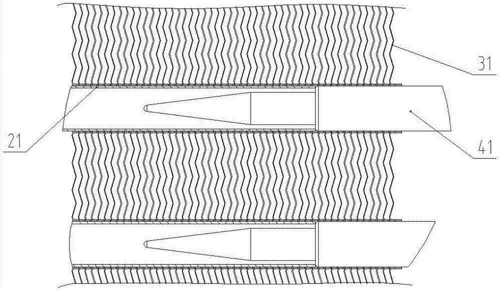
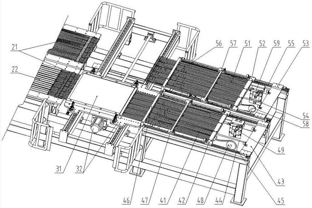
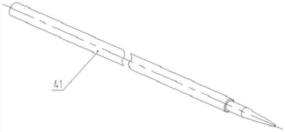
[0044] Such as Figure 1 to Figure 6 As shown, a U-shaped tube guiding device for automatic intubation machines for air-conditioning condensers and evaporator fins, the U-shaped tube guiding device includes a frame, two side rails 45, a guide pin 41, a fixed support plate 46, Guide pin movable bracket 47, guide pin push plate Ⅱ42, guide pin push plate Ⅰ43, guide pin drive cylinder 44, lift translation cylinder 49;

[0045] Among them, the guide rails 45 on both sides are installed in parallel on the rack, and the guide pin 41 fixed support plate is installed on the rack at the left end of the guide rails 45 on both sides and close to the fin group. On the guide rails 45 on both sides, from left to right, The guide pin movable bracket 47, the guide pin pusher plate II 42, and the guide pin push plate I 43 are provided. The two ends of the guide pin movable bracket 47, the guide needle push plate II 42 and the guide needle push plate I 43 are set on both sides On the guide rail sl...

Embodiment 2

[0050] This embodiment provides a U-shaped tube guide device for an automatic fin intubation machine for air-conditioning condensers and evaporators. The structure is as described in Example 1, and the difference is that: in the case of double rows of 36 U-shaped tubes For the fin group (18 U-tubes in a single row) as an example, when intubation is performed, 36 through holes for the guide pin to pass through are provided at equal intervals on the fixed support plate.

[0051] The guide pin movable bracket 47, 57 is divided into two parts, including an upper frame body and a lower frame body combined up and down. The lower surface of the upper frame body and the upper surface of the lower frame body are provided with 36 semicircular recesses of the same size. When the upper frame body and the lower frame body cooperate to form a whole groove, the semicircular groove of the upper frame body and the semicircular groove of the lower frame body combine to form 36 circular through hole...

Embodiment 3

[0054] This embodiment provides a U-shaped tube guide device for an automatic fin intubation machine for air-conditioning condensers and evaporators. The structure is as described in Embodiment 1, and the difference lies in: in order to move the guide pin bracket 47 and The rationality of the position between the guide pin push plate II 42 and the U-shaped tube guide device also includes a sprocket 481 and a chain plate 482. The sprocket 481 is arranged on the frame and is located under the guide pin push plate II 42. The plate 482 is arranged on the left and right sprockets 481. The upper and lower sides of the chain plate 482, namely the loose side and the tight side, are in a relaxed state in the initial stage. The bottom of the guide pin movable bracket 47 and the guide pin push plate Ⅱ 42 are both set On the chain plate 482. The guide pin pusher plate II 42 and the guide pin movable bracket 47 are fixed on the chain plate 482. The chain plate 482 gradually drives the sproc...


PUM


Abstract

The invention relates to a device and method for correcting a U-shaped pipe for an air conditioner condenser and evaporator fin automatic pipe inserting machine. The device comprises a machine frame, guide rails on two sides, a guide pin, a fixed supporting plate, a guide pin movable supporting frame, a guide pin push plate II, a guide pin push plate I, a guide pin drive cylinder and a lifting and horizontally-moving cylinder. The guide pin push plate I pushes the guide pin push plate II so that the guide pin which is locked by the guide pin push plate II and penetrates through the fixed supporting plate and the guide pin movable supporting frame can be inserted into a pipe opening of the U-shaped pipe after penetrating through a fin set, the guide pin play a good correcting role in the U-shaped pipe inserting work, and meanwhile the guide pin passively returns to the original position. The passive follow-up type U-shaped pipe correcting device corrects the U-shaped pipe to be freely and smoothly inserted through the guide pin, the resistance to the pipe inserting movement is reduced, the pipe inserting reliability is effectively ensured, the failure rate and the rejection rate are decreased, and the manufacturing cost is reduced.

Description

Technical field [0001] The invention relates to a U-shaped tube guiding device for an air-conditioning condenser and evaporator fin automatic intubation machine and a guiding method thereof, belonging to the technical field of air-conditioning condenser and evaporator fin U-shaped tube automatic intubation. Background technique [0002] Current air conditioning condenser and evaporator fin U-tube intubation is mainly realized by manual operation. Without the intubation guide device, the U-tube is inserted into the fin group at a time. Manual intubation has many problems such as high product rejection rate, high labor intensity, high technical requirements for personnel, and high labor costs. [0003] Existing air conditioning condenser and evaporator fin automatic intubation machine can replace manual automatic intubation of U-shaped tube. This automatic intubation machine can realize automatic feeding and positioning of U-shaped tube and automatic intubation of U-shaped tube. Act...

Claims


Application Information

Patent Timeline
Patent Type & Authority Patents(China)
IPC IPC(8): B23P19/12
CPCB23P19/12
Inventor 周军李卫范维康李丽红
Owner SHANDONG UNIV
Why Eureka
Try Eureka