Automatic movable material machining robot

A robot and mobile technology, applied in the direction of metal processing machinery parts, metal processing, metal processing equipment, etc., can solve the problems that cannot be applied to different sites, cannot cope with emergencies, replace processing parts, etc., and achieve automatic handling Effect

Active Publication Date: 2020-07-28
SHANDONG ZKSEASY INTELLIGENT TECH CO LTD
View PDF11 Cites 0 Cited by
  • Summary
  • Abstract
  • Description
  • Claims
  • Application Information

AI Technical Summary

Problems solved by technology

[0002] The existing material processing equipment usually needs to process the workpiece through a fixed machine tool, which cannot be applied to different sites. By searching the existing technology, it is found that the patent number is: 201620403872. 7 Chinese utility model patents disclose flexible material transmission Functional vertical machining center machine tool; each part forms a three-way motion relationship in space, in which the cross slide on the X-axis moves horizontally along the machine wall, driven by the X-axis drive system; the main shaft of the ram on the Z-axis moves along the The cross slide moves vertically up and down, driven by the Z-axis drive system; the upper table on the Y-axis moves back and forth horizontally along the bed, driven by the Y-axis drive system, and each drive system is controlled by the control system, and the synergy of the machine tool three-way drive;
[0003] However, the machining center machine tool can only realize three-way drive, cannot move, cannot cope with emergencies, and cannot replace processing parts according to different needs. Therefore, we urgently need to invent an automated mobile material processing robot to solve the above technical problems

Method used


Image

  • Automatic movable material machining robot
  • Automatic movable material machining robot
  • Automatic movable material machining robot

Examples


Embodiment Construction

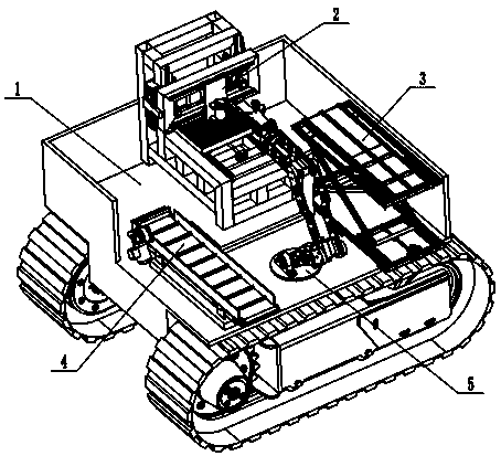
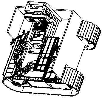
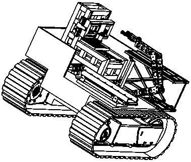
[0030] The technical solutions of the present invention will be further specifically described below through the embodiments and in conjunction with the accompanying drawings. In the following description, many specific details are set forth in order to fully understand the present invention, but the present invention can be implemented in many other ways different from those described here, and those skilled in the art can do similar Modifications, and therefore the present invention is not limited to the specific examples disclosed below.

[0031] In the description of the present invention, it should be noted that the orientation or positional relationship indicated by the terms "up", "down", "front", "rear", "left", "right" etc. are based on the Orientation or positional relationship, or the orientation or positional relationship that the inventive product is usually placed in use, is only for the convenience of describing the present invention and simplifying the descript...


PUM


Abstract

An automatic movable material machining robot comprises a walking mechanism, a machining mechanism, a lifting conveying mechanism, a discharging mechanism, a clamping and carrying mechanism and a control mechanism. The machining mechanism, the lifting conveying mechanism and the discharging mechanism are fixedly mounted on the upper end face of a supporting plate. The machining mechanism can carryout milling machining, the machining part can be replaced when needed on site, and machining of a milling machine, a grinding machine, a drilling machine and other machine tools is achieved. The lifting conveying mechanism is used for transporting machined materials. The discharging mechanism is used for transporting finished products. The clamping and carrying mechanism is rotationally mounted on an electric rotary shaft. The clamping and carrying mechanism is used for carrying the materials and the finished products. A lead screw motor drives a lead screw on a lifting connecting rod, and then an ejector plate ascends and descends. An electric roller is arranged on the upper end face of the ejector plate, a power driving device is arranged in the electric roller, and therefore the function of automatic ascending and descending and transferring the materials is achieved.

Description

technical field [0001] The invention relates to the technical field of automatic material processing, in particular to an automatic mobile material processing robot. Background technique [0002] The existing material processing equipment usually needs to process the workpiece through a fixed machine tool, which cannot be applied to different sites. By searching the existing technology, it is found that the patent number is: 201620403872. 7 Chinese utility model patents disclose flexible material transmission Functional vertical machining center machine tool; each part forms a three-way motion relationship in space, in which the cross slide on the X-axis moves horizontally along the machine wall, driven by the X-axis drive system; the main shaft of the ram on the Z-axis moves along the The cross slide moves vertically up and down, driven by the Z-axis drive system; the upper table on the Y-axis moves back and forth horizontally along the bed, driven by the Y-axis drive syste...

Claims


Application Information

Patent Timeline
Patent Type & Authority Applications(China)
IPC IPC(8): B23Q37/00B23Q7/04B23Q1/26B23Q5/40B62D55/06
CPCB23Q37/00B23Q7/04B23Q1/26B23Q5/40B62D55/06
Inventor 闫九友
Owner SHANDONG ZKSEASY INTELLIGENT TECH CO LTD
Why Eureka
Try Eureka