Isolation insulation method with resistor chip clamped through integral insulation tube and resistor unit
A technology of overall insulation and resistance sheet, applied in the direction of I-shaped/sinusoidal resistance elements, etc., can solve the problems of shortening the creepage distance, affecting the insulation performance of resistance units, and failing to meet the high-voltage requirements of the rainy environment, so as to achieve simplified isolation way, improve the overall insulation performance, and meet the effect of high voltage resistance requirements
- Summary
- Abstract
- Description
- Claims
- Application Information
AI Technical Summary
Problems solved by technology
Method used
Image

Examples
Embodiment 1
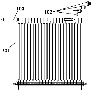
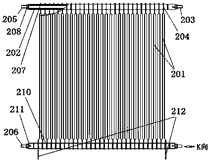
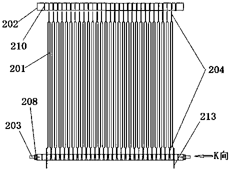
[0035] by attaching Figure 2-5 It can be seen that the present invention relates to a resistance unit with a combination structure of resistance bands, including a support rod 203, a resistance band 201, a whole insulating tube 202 and a conductor 212, through which the support bar 203, the resistance band 201 and the whole insulating tube 202 are combined The two ends of the resistance band 202 are isolated and positioned through the entire insulating tube 202 to form a resistance unit.
[0036] The support rod 203 is a cylindrical metal rod commonly called a tie rod, and there are two support rods 203, which are respectively the first support rod 205 and the second support rod 206; the first support rod 205 and the second support rod The supporting rods 206 are respectively located at the ends 204 of the upper and lower ends of the resistance band 201, and pass through the central hole 207 on the entire insulating tube 202, and the two ends extend out of the entire insulati...
Embodiment 2
[0043] The principle of embodiment two is the same as embodiment one, but the structure of the insulating tube is slightly different, and the different parts are as attached Figure 6-8 As shown, it is a resistance unit with a combination structure of resistance bands, including a support rod 303, a resistance band 301, and an integral insulating tube 302. The resistance unit is formed by combining the support bar 303, the resistance band 301 and the integral insulating tube 302. Its characteristics are The two ends of the resistance band 301 are isolated and positioned through a toothed integral insulating tube 302 .
[0044] It’s just that the overall composite polymer insulation tube 302 is an overall composite polymer insulation tube made of composite polymer materials. The cross-sectional shape of the overall composite polymer insulation tube is a multi-tooth shape, which is convenient for the overall composite polymer insulation tube 302 to connect the resistance band 301...
Embodiment 3
[0049] The principle of the third embodiment is the same as that of the second embodiment. It uses an integral composite polymer insulating tube, but the direction of the "C"-shaped opening on the resistance band is slightly different, and the directions of the openings are perpendicular to each other. Among them One end of the opening is on the top of the resistance band, and the other end is on the side of the resistance band, so that the overall composite polymer insulating tube snaps into the "C" opening on the resistance band more flexibly.
[0050] The cross-section of the overall composite polymer insulating tube can be in various cross-sectional shapes, such as circular, elliptical, arbitrary polygonal or multi-toothed structures (as shown in the attached Figure 9 shown), and has a card slot on the round, arbitrary polygonal or multi-toothed surface.
PUM
 Abstract
Description
Claims
Application Information