Coil winding, coil module, transmitting device, receiving device, system and terminal

A coil winding and coil technology, applied in the direction of transformer/inductor coil/winding/connection, circuit device, battery circuit device, etc., can solve the problem of low wireless charging efficiency and achieve the effect of improving wireless charging efficiency

Active Publication Date: 2019-09-27
HUAWEI TECH CO LTD
View PDF6 Cites 13 Cited by
  • Summary
  • Abstract
  • Description
  • Claims
  • Application Information

AI Technical Summary

Problems solved by technology

[0005] The application provides a coil winding, a coil module, a transmitting device, a receiving device, a s

Method used


Image

  • Coil winding, coil module, transmitting device, receiving device, system and terminal
  • Coil winding, coil module, transmitting device, receiving device, system and terminal
  • Coil winding, coil module, transmitting device, receiving device, system and terminal

Examples


Embodiment Construction

[0080] In order to make the purpose, technical solution and advantages of the present application clearer, the implementation manner of the present application will be further described in detail below in conjunction with the accompanying drawings.

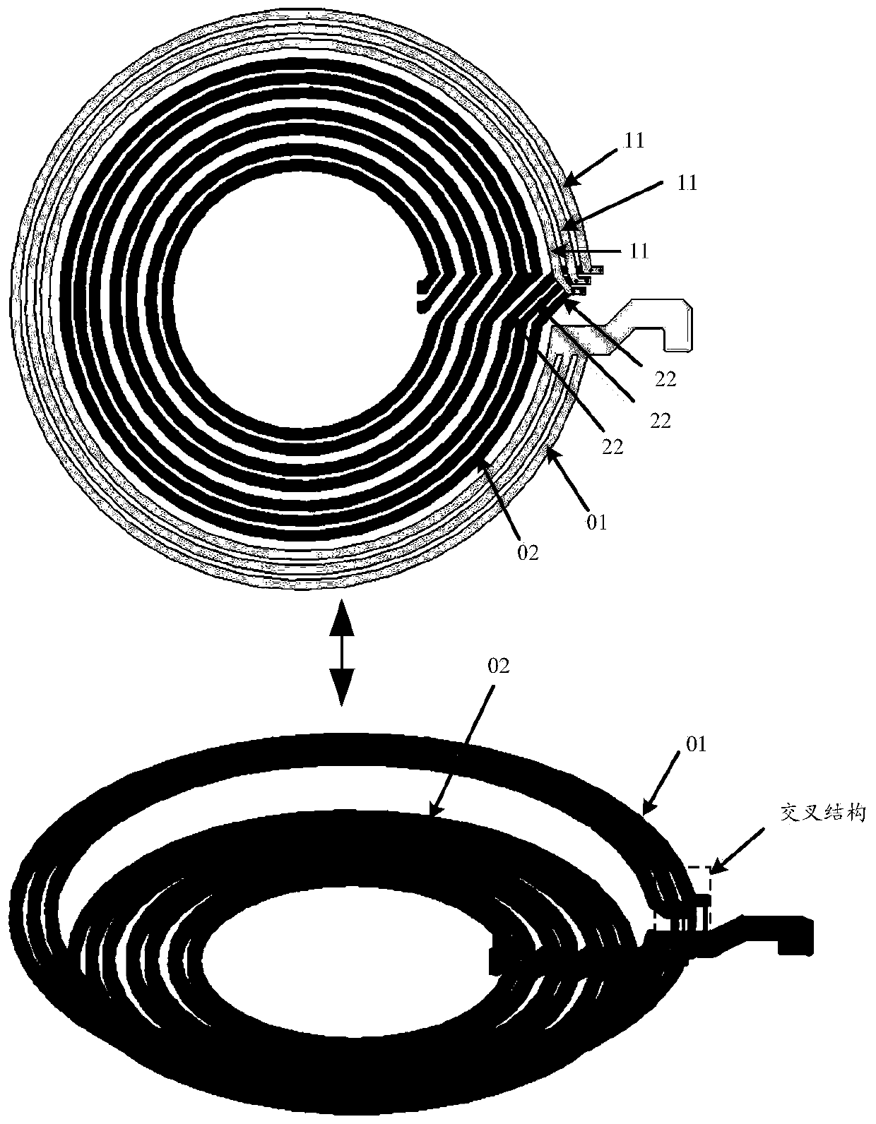
[0081] image 3 It is a structural schematic diagram of a coil winding provided in an embodiment of the present application. see image 3 , the coil winding includes: an insulating layer, a first partial coil located on one side of the insulating layer, and a second partial coil located on the other side of the insulating layer.

[0082] The first part of the coil includes a first segment of wire 01 having N slots, and the first segment of wire 01 is divided into N+1 strands of first sub-wires 11 by the N slots. The second partial coil includes a second section of wire 02 which also has N slots, and the second section of wire 02 is also divided into N+1 second sub-wires 22 by the N slots it has. Wherein, N is an integer greater...


PUM


Abstract

The present application discloses a coil winding and belongs to the technical field of wireless charging. The coil winding includes an insulating layer; a first partial coil on one side of the insulating layer; and a second partial coil on the other side of the insulating layer. The first partial coil comprises a first wire section. The second partial coil comprises a second wire section. The first wire section and the second wire section each have N slots. The first wire section is divided into N+1 first sub-wires by its N slots. The second wire section is divided into N+1 second sub-wires by its N slots. The N+1 first sub-wires and the N+1 second sub-wires are electrically connected to each other one to one to form N+1 pairs of sub-wires. At least one cross structure is formed in the N+1 pairs of sub-wires. The ring current loss in the coil winding can be reduced and the wireless charging efficiency can be improved. In addition, the present application also discloses a corresponding coil module, a wireless charging transmitting device, a wireless charging receiving device, a wireless charging system, and a terminal.

Description

technical field [0001] The present application relates to the technical field of wireless charging, in particular to a coil winding, a coil module, a transmitting device, a receiving device, a system and a terminal. Background technique [0002] Currently, it is becoming more and more popular to use wireless charging technology to charge electronic devices. Devices that implement wireless charging technology are called wireless chargers. In a specific implementation, the wireless charger is provided with a transmitting coil, and the electronic device is provided with a receiving coil. The alternating current carried by the transmitting coil in the wireless charger generates a magnetic field, and the receiving coil in the electronic device generates a voltage through magnetic coupling, thereby Realize the charging of electronic equipment. [0003] Since wireless charging is based on the magnetic coupling between the transmitting coil and the receiving coil for energy transm...

Claims


Application Information

Patent Timeline
IPC IPC(8): H01F38/14H01F27/28H01F27/34H02J50/12H02J50/70
CPCH01F27/2871H01F27/34H01F38/14H01F2027/348H02J50/12H02J50/70H01F27/2804H02J50/402H01F27/2823H01F27/32H02J7/02H02J50/10
Inventor 朱勇发陈晓威曾智强
Owner HUAWEI TECH CO LTD
Why Eureka
Try Eureka