Manufacturing method for power distribution module of new energy automobile

A technology for new energy vehicles and power distribution, which is applied in the manufacture of secondary batteries, circuits, electrical components, etc., can solve the problems of complex binding process of power distribution module covers, difficulty in power distribution modules having the same size, and unreliable binding, etc. Simple, labor-intensive, and firm binding

Inactive Publication Date: 2019-09-27
义乌纹挺新能源科技有限公司
View PDF0 Cites 6 Cited by
  • Summary
  • Abstract
  • Description
  • Claims
  • Application Information

AI Technical Summary

Problems solved by technology

[0002] At present, with the development of society, the use of new energy vehicles has gradually replaced traditional gasoline vehicles. When the power distribution module in new energy vehicles is manufactured, a cover needs to be bound on its outer surface. Currently, the power distribution module cover binding device There are a lot of equipment, and the binding process of the cover of the power distribution module is relatively complicated, and the binding is not reliable. During the use of the power distribution module, the cover is easy to fall off. There are also perfect binding devices on the market, but the process is complicated and often divided into several steps. First, the cover is cut, then positioned, and finally glued, but the problem is that the bound cover of the power distribution module may be tilted, and manual cutting is difficult to ensure that the size of each cut power distribution module is the same

Method used


Image

  • Manufacturing method for power distribution module of new energy automobile
  • Manufacturing method for power distribution module of new energy automobile
  • Manufacturing method for power distribution module of new energy automobile

Examples


Embodiment Construction

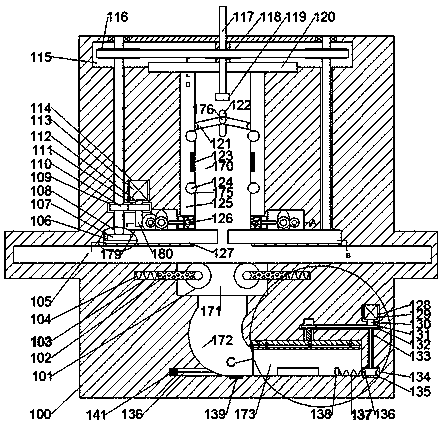
[0024] Combine below Figure 1-7 The present invention is described in detail, and for convenience of description, the orientations mentioned below are now stipulated as follows: figure 1 The up, down, left, right, front and back directions of the projection relationship itself are the same.

[0025] refer to Figure 1-7 , a manufacturing method of a new energy vehicle power distribution module according to an embodiment of the present invention, including a fuselage 100, wherein a first pulley cavity 115 is provided on the inner upper side of the fuselage 100, and the first belt The lower side of the wheel cavity 115 is provided with a power distribution module discharge space 170 with an opening forward. The left and right end walls of the power distribution module discharge space 170 are symmetrically provided with a pair of centering clamping devices. A gluing device is arranged on the outside, and a power space 114 is arranged on the left side of the gluing device on the ...


PUM


Abstract

The invention discloses a manufacturing method for a power distribution module of a new energy automobile. The module comprises a robot body, and a power distribution module discharging space with a forward opening is formed in the machine body. A centering clamping device is symmetrically arranged on the left end wall and the right end wall of the discharging space of the power distribution module; a gluing device is arranged on the outer side of the centering clamping device; a locking device is arranged on the lower end wall of the discharging space of the power distribution module in a bilateral symmetry manner; a cutting space is formed in the lower side of the interior of the machine body; a cutting device is arranged on the upper side of the cutting space; a driving space is formed in the upper side of the cutting device; and a driving motor is fixedly arranged on the upper end wall in the driving space. The module further comprises an auxiliary cutting device driven by the same driving motor, the module enables binding to be firmer in an adhesive binding mode, the manual cutting is not needed, the labor intensity is reduced, binding efficiency is improved through one step from the binding process to the forming process, and the auxiliary cutting device enables the cutting position to be more accurate.

Description

technical field [0001] The invention relates to the technical field of binding and processing of power distribution modules, in particular to a method for manufacturing a power distribution module of a new energy vehicle. Background technique [0002] At present, with the development of society, the use of new energy vehicles has gradually replaced traditional gasoline vehicles. When the power distribution module in new energy vehicles is manufactured, a cover needs to be bound on its outer surface. Currently, the power distribution module cover binding device There are a lot of equipment, and the binding process of the cover of the power distribution module is relatively complicated, and the binding is not reliable. During the use of the power distribution module, the cover is easy to fall off. There are also perfect binding devices on the market, but the process is complicated and often divided into several steps. First, the cover is cut, then positioned, and finally glued...

Claims


Application Information

Patent Timeline
Patent Type & Authority Applications(China)
IPC IPC(8): H01M10/04H01M2/10
CPCH01M10/0404H01M50/20Y02E60/10Y02P70/50
Inventor 徐江海郑艳梅
Owner 义乌纹挺新能源科技有限公司
Why Eureka
Try Eureka